- взЕЯЭиХрбЕ,зЈзЂгкЮЂВЈЁЂЩфЦЕЁЂЬьЯпЩшМЦЙЄГЬЪІЕФХрбј
ЪзвГ > AWR > AWRЙйЭјFAQ > Interconnect or Bridgecode Not Drawn Between Component and Discontinuity Model
Interconnect or Bridgecode Not Drawn Between Component and Discontinuity Model
ТМШыЃКedatop.com ЕуЛїЃК
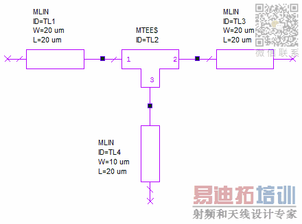
When a component is directly connected to a discontinuity model such as a MTEE, MBEND, MTAPER, etc there is no interconnect or bridgecode drawn.
This is by design. The discontinuity models (MTEE, MTAPER, MCORSS etc.) don't draw the bridgecode, only the lines draw the bridgecode (generate interconnect). You must use a line model along with any discontinuity model in order to create an interconnect. The bridge code will draw where the line area would be, not where the discontinuity would be.
Below is an example of the wrong and right way to do this. The schematic connected incorrectly is below.

The 3D layout is shown below, notice how the lines are not connected to the cap.

The correct scheamtic is below, notice the lenght of lines between the cap and the tapers.

The 3D layout is shwon below, notice how all the proper bridge code is drawing to make the connections between the lines and the cap.

Below is an example showing why the bridge code needs to draw the way it does. Here is the schematic.
The metal for the MTEE is a different metal than the lines, notice how the bridge code draws outside the area of the MTEE.

Here is how the layout would look if the bridge code draw over the discontinuity, this would cause DRC errors with the shapes being to close together.

Other obvious case would be for a capacitor and a line where the bridge code needs to bridge from a lower level line to the top of the cap, involving a via. If this via were drawn in the layout for the capacitor it would short out the capacitor.
AWR Microwave Office ХрбЕПЮГЬЬззАЃЌЪгЦЕНЬбЇЃЌАяжњФњПьЫйбЇЯАеЦЮеMWO...
ЩЯвЛЦЊЃКIs my License V11 or V12
ЯТвЛЦЊЃКIntelliSense Is Not Working in Visual Basic Editor
MWOХрбЕПЮГЬЭЦМіЯъЧщ>>
 Microwave officeзЈвЕЯЕЭГЕФЪгЦЕХрбЕЬззАЃЌАяжњФњДгСуПЊЪМЃЌШЋУцбЇЯАMWOЕФЩшМЦгІгУЁОMore..ЁП
CSTРИФП
ЦЕЕРзмХХаа
- Which CPW Line Models Support
- Problem Saving Layout Rulers in
- Calculate 3dB Bandwidth of Band
- AWR&'s GERBER File Format Details
- Using DXF Format with the AWR
- DXF Files Do Not Open in AutoCAD
- FAQ: Using Encrypted HSPICE Netlists
- Touchstone File Repair Utility
- How Can I Fix the Shorted Cir
- Failure initializing the AWR Sc