- 易迪拓培训,专注于微波、射频、天线设计工程师的培养
Designing LNA with FHX13LG in AWR
录入:edatop.com 点击:
Hi everyone
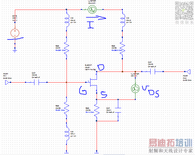
I want to design an LNA with FHX13LG transistor. We know that for this transistor there is only s2p file. My question is that how should I make the dc biasing circuit using the s2p file. I tried it on my own but when I'm changing the values for Resistors , the current (I) changes , but the Vds stays the same as the dc voltage source.(if I chose the dc voltage source 2 volts, Vds changes to 2 volts too)
I want to design an LNA with FHX13LG transistor. We know that for this transistor there is only s2p file. My question is that how should I make the dc biasing circuit using the s2p file. I tried it on my own but when I'm changing the values for Resistors , the current (I) changes , but the Vds stays the same as the dc voltage source.(if I chose the dc voltage source 2 volts, Vds changes to 2 volts too)
Yes, of course the currents and voltages stay the same if you use linear measured data (s2p) where the measurement was done at one fixed bias point.
You can include the bias layout in the linear MWO simulation, but the transistor will not "see" the supply and voltage changes. You need to think about the yourself without help from the simulator. It's not complicated, use the information from the transistor data sheet.
You cannot use s-parameters in Mixer ( or general speaking, nonlinear ) simulations.You should find a proper nonlinear model.
In additional to this, you don't have to have nonlinear model for this transistor because if the transistor works under mentioned operating and bias condition,its NF will hopefully be as measured and mentioned in its datasheet so therefore you don't have to simulate in nonlinear region.Just match it in according to NFmin impedance and try it on a proper board with playing around bias voltages/currents.
So, s-parameters ( NF information ) are good enough to obtain a performance in term of Noise.The others can be tweaked on the board.
Thanks BigBoss. I think you are right. I did as you said and looks like the results for NF are right.
AWR Microwave Office 培训课程套装,视频教学,帮助您快速学习掌握MWO...
上一篇:Connecting matlab to Microwave Office
下一篇:AE-427 and AE-417 transistors AWR microwave office