- 易迪拓培训,专注于微波、射频、天线设计工程师的培养
Waveguide S11 in CST MWS
录入:edatop.com 点击:
Hi,
I face following problem:
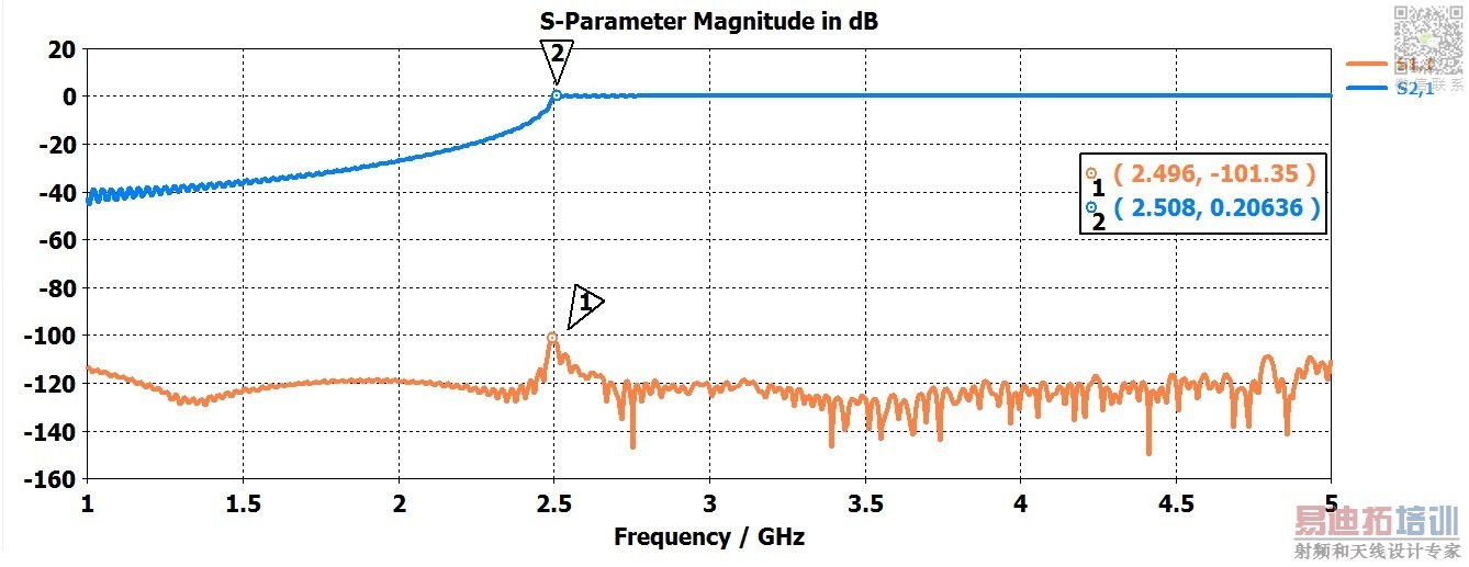
When I run simulation for simple rectangular waveguide in frequency range that includes cutoff frequency, I'm suppose to see the change in S-parameters, that show the cutoff behaviour of the wavegude. My S21 looks ok, but S11 is not showing what I think it should. Below cutoff frequency S11 should be around 0 dB and above it should drop. Am I wright? Can anyone tell me where could be the problem?
I am using transient solver.
Thanks
I face following problem:
When I run simulation for simple rectangular waveguide in frequency range that includes cutoff frequency, I'm suppose to see the change in S-parameters, that show the cutoff behaviour of the wavegude. My S21 looks ok, but S11 is not showing what I think it should. Below cutoff frequency S11 should be around 0 dB and above it should drop. Am I wright? Can anyone tell me where could be the problem?
I am using transient solver.

Thanks
Below the cutoff frequency means that the wave doesn't propagate in the wave guide, but does this also mean that the wave is reflected to the source port?
Agreed. This is because the reference impedance is not what you expect.
Your S11 refers to the waveguide input impedance at the port ("generalized S-parameters) instead of a fixed impedance. So if the DUT is just a straight waveguide segment, these generalized S-parameters will show perfect match at all frequencies (even below cutoff) because the DUT imput impedance is identical to the reference impedance.
i have same problem too..do you know how to get the correct S11?what should i change in the design?can u please show me how to get the correct S11?
In case of using transient solver, you should change your frequency range, fmin should be above cutoff frequency of your waveguide.
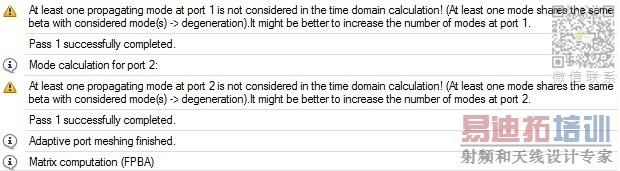
im design 6cm x 6cm rectangular waveguide..cutoff frequency=2.49Ghz..I change the fmin to 3Ghz and fmax 10Ghz..but still didnt get the correct S11..is it have some problem in excitation signal?boundary condition?or what setting should i check?u can see before i changed fmin and after i changed fmin in the result that i attach..i also have some warning message when i run the solver..please help me solve this problem..
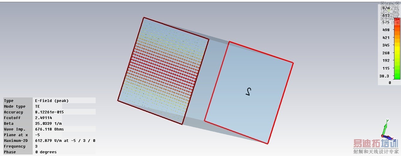
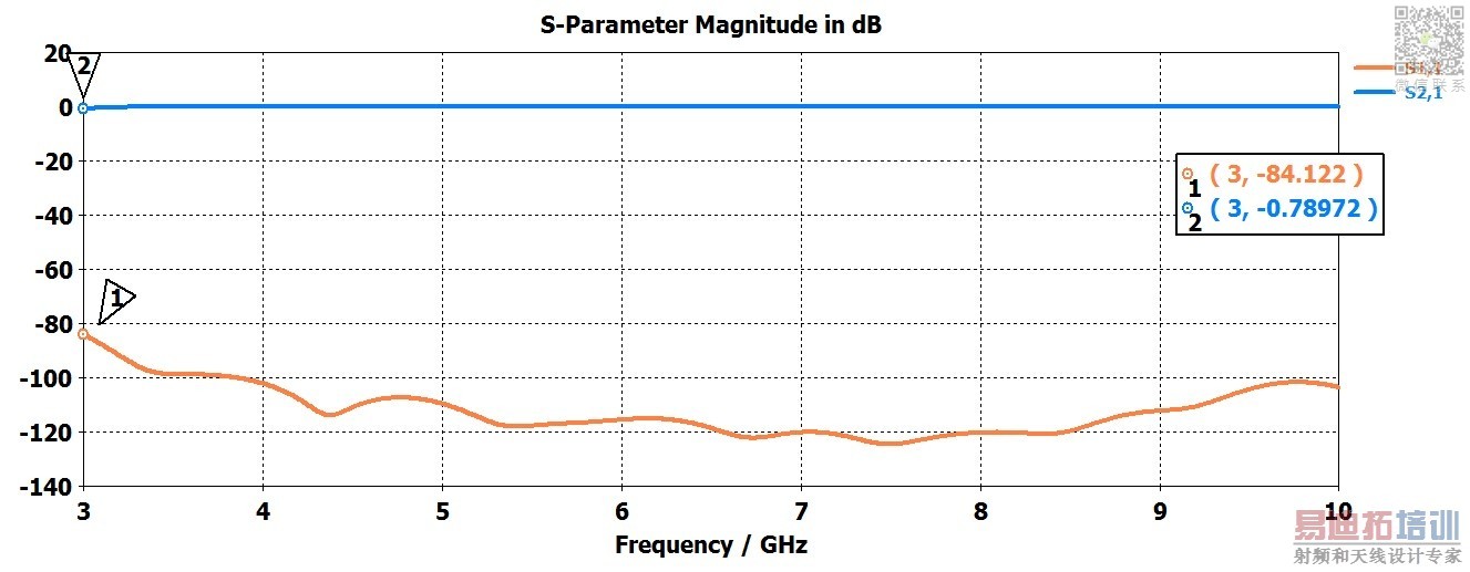
I believe it is a correct result ! As volker_muehlhaus wrote, your S11 refers to the port impedance and port impedance changes with frequency, so you will get perfect match at all frequencies. If you want your results to be normalized to fixed impedance, you have to check the box "normalize to fixed impedance" in transient solver options and put there desired value.
The warning only means, that in square waveguide both TE10 and TE01 have the same cutoff frequency so in port definition you should change number of modes from 1 to 2.
申明:网友回复良莠不齐,仅供参考。如需专业解答,请学习易迪拓培训专家讲授的CST视频培训教程。
