- взЕЯЭиХрбЕ,зЈзЂгкЮЂВЈЁЂЩфЦЕЁЂЬьЯпЩшМЦЙЄГЬЪІЕФХрбј
ЪзвГ > ЬьЯпЩшМЦ > RFID/NFCЬьЯпЩшМЦНЛСї > need schematic to design ask modulator for 1Mbps data and 13.56Mhz
need schematic to design ask modulator for 1Mbps data and 13.56Mhz
ТМШыЃКedatop.com ЕуЛїЃК
hi
i am little bit knew about electronics basics.i am really mad about how to design ask modulator . from about 2 weeks i tried some circuits available in google. but i couldn't get the required rectangular output. plz anybody give me awareness about how to design ask modulator circuit . i have to give the ask input to class e amplifier.
thanks in advance
ASK means amplitude keying. What is the digital signal? If it is TTL, you can use it to bias a simple transistor amplifier at 13.56 MHz, or a diode switch.
You possibly will not get a "rectangular" output at13.56 MHz but RF bursts you can see of a good 20-MHz oscilloscope. Make sure your RF signal source and load are matched to 50 Ohms as well as the oscilloscope.
On receiving end, be ready to adjust RF signal level to detector for an optimum detected pulse shape, and use a fast comparator (MAX 999) or a TTL gate like 7400 to reshape the baseband signal.
If your receiver has an AGC, make sure it response is slow to pass the 1Mb/s ASK signal.
plz give me some simple ask modulator circuit which will give rectangular ask output it will help me to understand about it . i tried circuits as in attached ones but i couldn't
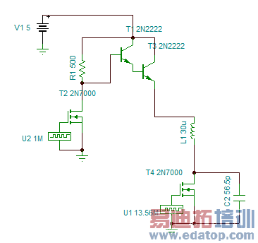
I do not see any attached circuit. As I wrote, take a RF transistor amplifier with an adjustable base bias potentiometer and through a 100 Ohm resistor add your pulses to the bias. Adjust the bias so that the transistor is open at pulse maximum And closed when the pulse is at zero.
You never mentioned what pulse amplitude is. Take care you do not kill the transistor.
Even simpler is a diode switch, only at 13.56 MHz you cannot use a PIN diode, so the on/off ratio may be only some 16 dB with a diode.
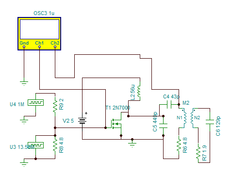
Now I can see the circuits, but they do not make any sense.Where is the RF signal source to be ASK modulated? WhAt is the pulse amplitude and data rate to be used as baseband?
i am applying data with clock source of datarate 1Mbps i.e 1Mhz ,actually pulse amplitude is 3.3V.
So your data do come as TTL. THen try what I suggested: couple your data stream through 1 nF capacitor to the base of a RF transistor amplifier, and adjust its DC bias for the best ASK output pattern (use an oscilloscope with 50-Ohm input impedance).
You can also use a switch, which is controlled by 1M TTL signal, to switch on or off the 13.56M RF signal.
I am getting the output like as shown in attachment output.png when i connected oscilloscope across coils of class e amplifier. but i unable to get as an ask waveform(i.e. rectangular). what i have to vary .i tried by changing inductance(choke) also i varied shunt capacitance which is present across drain. but i cant. plz give me ny one some awareness about this circuit.
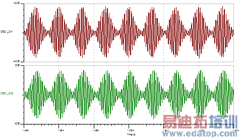
can not read that scale, but are u sure the scope is not aliasing?
try using one of these: sn74cbt1g125dbvr
or maybe just a CMOS AND gate that is fast enough for 14 MHz.ON-14 MHz square wave out, OFF-nothing out.can lowpass filter with two caps and an inductor
ЩъУїЃКЭјгбЛиИДСМнЌВЛЦыЃЌНіЙЉВЮПМЁЃШчашзЈвЕбЇЯАЃЌЧыВщПД13.56MHz NFC/RFIDЬьЯпЩшМЦХрбЕПЮГЬЁЃ
ЩЯвЛЦЊЃКЬсЙЉИпадМлБШNFCЬьЯпгУЩеНсЬњбѕЬхЦЌ
ЯТвЛЦЊЃКЦЌЩЯЬьЯпЕФЮЪЬт
13.56MHz ЯпШІЬьЯпЩшМЦЯъЧщ>>
 ШЋУцНтЮі 13.56MHz NFC/RFID ЯпШІЬьЯпЕФдРэгыЩшМЦ, ЬьЯпЦЅХфЕчТЗЕФЩшМЦЕїЪд,вдМАHFSSЗТецЗжЮіЕФШЋЙ§ГЬЁОMore..ЁП
ЪжЛњЬьЯпЩшМЦХрбЕНЬГЬЯъЧщ>>
 ЙњФкзюШЋУцЁЂЯЕЭГЁЂзЈвЕЕФЪжЛњЬьЯпЩшМЦХрбЕПЮГЬ,УЛгажЎвЛ;ЪЧФњбЇЯАЪжЛњЬьЯпЩшМЦЕФзюМббЁдё...ЁОMore..ЁП
ЮЂаХЙЋжкКХ

ЩЈУшЖўЮЌТыЙизЂЮвУЧЕФЮЂаХЙЋжкКХ
ЙизЂКѓЪзДЮЙКТђБОеОПЮГЬПЩЯэЪмОХелгХЛн
ЬьЯпЩшМЦРИФП
ЦЕЕРзмХХаа
- ADSЗТец13.56M PCBЬьЯп --гаЭМгаецЯр
- вЛАуPETдк920MHzЪБНщЕчГЃЪ§ЖрЩйЃП
- 13.56M RFIDЬьЯпЕФДЋЪфОрРыШчКЮВтЪд
- ГЌИпЦЕгыЕЭЦЕЁЂИпЦЕRFIDЕчзгБъЧЉЕФЧјБ№
- RFIDЬьЯпзшПЙЁЂs11ВЮЪ§ШчКЮВтЕУЃП
- 13.56mЬьЯпЕФжааФЦЕТЪЪЧ13.56mТ№ЃП
- ЮЂДјЬьЯпгУSMAНгЭЗКИНг
- rfidБъЧЉЬьЯпДјПэЕНЕзвд-3dbвдЯТЛЙЪЧ-
- Йигк13.56MЬьЯпЕФЮЪЬт
- гУHFSSЗТецRFIDБъЧЉЬьЯпЕФЮЪЬт