- 易迪拓培训,专注于微波、射频、天线设计工程师的培养
Simulate 13.56M Loop PCB Antenna Use ADS Problem
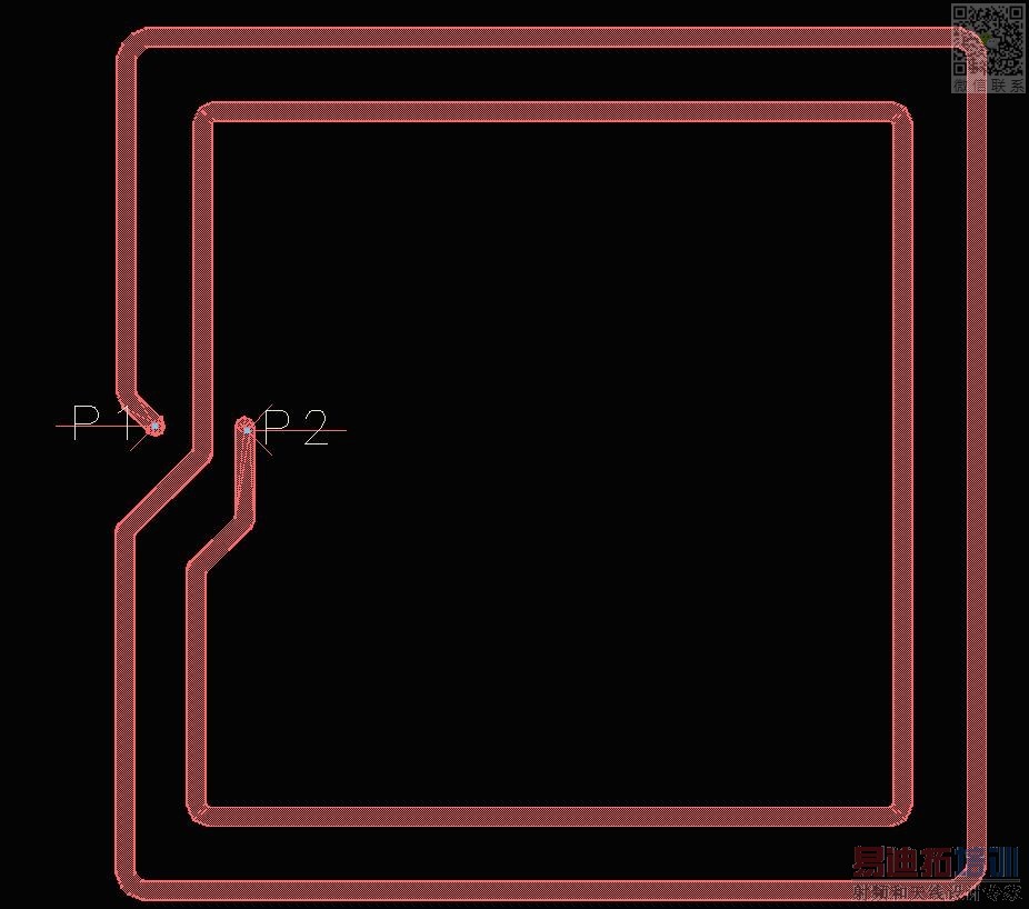
PCB Antenna Picture
Port1 Setting
Port2 Setting
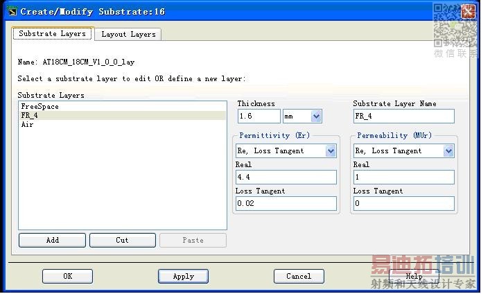
Substrate setting
Layout Layers Setting
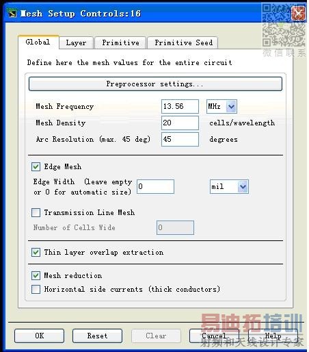
Mesh Setting
Simulation Setting
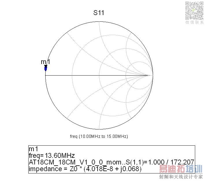
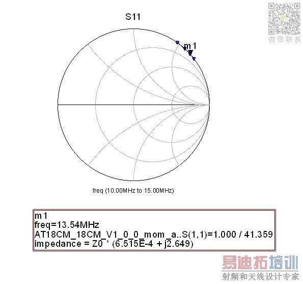
Simulation result
Actual measure result S11 of the pcb antenna
From the simulation result, we know this impedence is 50*(4.02E-8 + 0.068j), it?s equivalent circuit is a resistor series a inductor, the resistor?s value is 50×4.02E-8, and the inductive reactance is 50×0.068 = 3.4 = jwL = 2*3.14*13.56 E6 => L= 0.0399uH, but I use Vect Network Analyser to measure this antenna?s inductor value is 1.6uH, so why ?
This is my Project , Can somebody help me?
13M56_Ant_prj.rar
RFID coil is effectively a pure AC magnetic problem that don't need a full featured EM solver. Nevertheless should it give correct results. I read about a cellsize setting of 20 cells/wavelength, which refers to a cell size of about 1.1 m. Don't know if this is a problem.
Hello everybody!
This problem is solved, the real size of the antenna is 180mm * 180mm, but the layout is 180mil * 180mil, so it is wrong. When I change the scale , the simulate result is very close to the true result. Select the layout then chose edit-》 scale.
Nice fault. Would be interesting, if you get realistic resistive impedance part as well when putting in copper conductivity.
申明:网友回复良莠不齐,仅供参考。如需专业帮助,请学习易迪拓培训专家讲授的ADS视频培训课程。
上一篇:ADS DXF/DWG import problem
下一篇:ads soft
 国内最全面、最专业的Agilent ADS培训课程,可以帮助您从零开始,全面系统学习ADS设计应用【More..】
- Agilent ADS教学培训课程套装
- 两周学会ADS2011、ADS2013视频教程
- ADS2012、ADS2013射频电路设计详解
- ADS高低阻抗线微带滤波器设计培训教程
- ADS混频器仿真分析实例视频培训课程
- ADS Momentum电磁仿真设计视频课程
- ADS射频电路与通信系统设计高级培训
- ADS Layout和电磁仿真设计培训视频
- ADS Workspace and Simulators Training Course
- ADS Circuit Simulation Training Course
- ADS Layout and EM Simulation Training Course
- Agilent ADS 内部原版培训教材合集

