- 易迪拓培训,专注于微波、射频、天线设计工程师的培养
cross-pair oscillator in ADS
录入:edatop.com 点击:
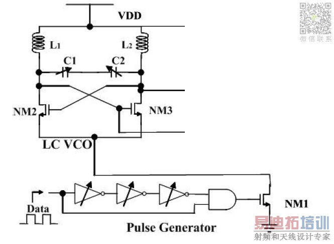
Hello there! I'm new in oscillator's designs and I need some advice. I'm trying to design this cross pair oscillator for a 868 MHz frequency:
But instead of using MOSFET I have to use BJT to lower the transistor's capacitances.
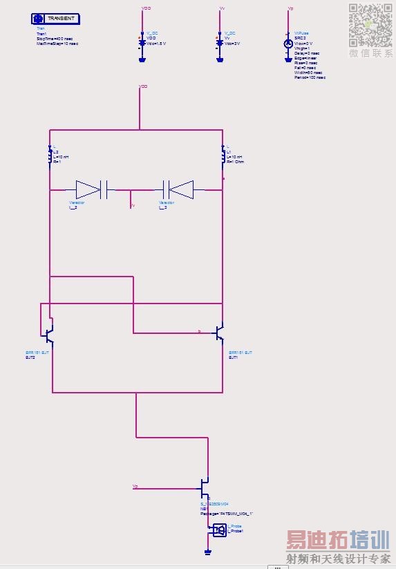
I have some trouble here because I can't obtain the oscillation. Here is my ADS design:
I'm using a presonalized varactor block so It could be the problem.
Any advice?
Ty all!
Non-symmetry is often helpful to get the action going in this type of oscillator. That is why I made the upper bias resistors unequal values.
The easy way to adjust frequency is by altering bias through one or more transistors.
The problem appears when i'm trying to bias the bottom mosfet with a DC 1.8V pulse. I need the oscillator to turn on and turn off to get a OOK modulation, this is the reason that i'm trying to switch it with a pulse source.
When I do this with the DC pulse source I get the "timesteap is too small" error. I've tried to increase the rise/fall of the source because I know that sometimes it fix the problem, but it doesn't work this time. I know that the problem is caused by that pulse source because the oscillator works fine with a DC source of 1.8V so probably it's something related to an voltage/intensity that grows too much when I switch the source.
Any advice/tips?
Ty very much, I don't know what I had done without your advices!
P.D: How do you take a picture of your whole schematic?
But instead of using MOSFET I have to use BJT to lower the transistor's capacitances.
I have some trouble here because I can't obtain the oscillation. Here is my ADS design:
I'm using a presonalized varactor block so It could be the problem.
Any advice?
Ty all!
I find my simulation will not oscillate with a capacitor in that position. The coils are sufficient to provide time-dependent behavior.
It also needs a diode across each coil. Otherwise high voltage spikes come from the coils.

Non-symmetry is often helpful to get the action going in this type of oscillator. That is why I made the upper bias resistors unequal values.
The easy way to adjust frequency is by altering bias through one or more transistors.
Hello BradtheRad and ty for your time and your simulation.
I have gotten the oscillation with my design by changing the NMOS for an ideal current source and by swapping the varactors. I got my non-simmetry by a ideal current source pulse in the tank, to start the oscillation. It worked well but I got some annoying harmonics that I have to erradicate to improve the oscillation.
So, at the moment I'm trying to do the same but with the original design, with NMOS instead of BJT but I can't get the oscillation. Do you know if have I to add something else to my simulation?
The question is: May I change these BJT for NMOS without changing other things?
I'm trying a simulation. It is necessary to apply a jolt, or shock, or instigation, in order to start oscillations. For instance, disconnected a wire momentarily.
Once started, oscillations will continue.
-Have you ever checked the negative impedance which is presented by active VCO? If you have which value have you found @868MHz ?
-Have you verify that real part of (negative) this impedance is sufficiently large compare to Tank Circuit Equivalent Resistance ? It should be at least 2.5 times greater than Tank Circuit Equivalent Resistance.
So ABS{R(active)}>2.5 ABS{Rtank} ( Rule of thumb !)
-Have you verify that Closed Loop Gain>1 and Closed Loop Phase=0 ?by aid of Differential Oscillator Probe in ADS ?
-Who said using BJT will bring lower capacitance compare CMOS ? It's totally depending on the process which you intend to use.
-What about "Start-Up" condition ? Have you provide that to excite the VCO ? Otherwise it will-perhaps- not start-up in ADS.
Oscillator design is state-of-art, you should commence from basic to complex.Don't take them all into account at first sight.
Ty for your answers!
BradtheRad did you finally get the oscillation with NMOS?
BigBoss:
-I'm using a ideal inductance right now and a couple of capacitors instead the varactors, so the negative resistence of the NMOS should be large enough to mantain the oscillation. The G of the NMOS are 80mS so Ra=-2/gm = 25ohm. It should work or am I wrong?
-I haven't check those oscillation parameters, I thought that with the negative resistence was enough.
- I'm using a diferencial pulse current source to start-up the oscillation in ADS. It worked fine with the BJT.
If the real part of Input Impedance of the active part is 25 Ohm, parallel equivalent resistance of your tank circuit should have minimum 75 Ohm or more.Have you checked that ? ( if you use ideal inductor it will be but with a real indcutor you would be surprized..)
You should also take the series resistance of the varactor into this math by converting these series resistances onto equivalent parallel resistance metioned above.
Don't forget Cgd and Cgs and Cgb capacitances for VCO frequency.
In this case the non-symmetry needs to be more definite. This is because the mosfets are voltage controlled (whereas transistors are current-controlled).
The imbalance can easily be achieved by applying unequal volt levels to the mosfet gates.
This simulation shows that the circuit is likely to remain stagnant, until a resistor is switched in so as to reduce voltage at the gate of one mosfet.

Ty very much, both of you! I have been working with the BJT oscillator and it works fine. I haven't been able to start the MOSFET one, but I'm going to try it again.
I have a last question for you, do you know how get the RMS of a signal in ADS? I saw that there is a rms() function but it works with the function points instead of the whole signal, so it returns me another sinusoidal function instead of one constant value. I'm trying to get the power dissipation of my circuit and I need those RMS values, isn't it?
Can't give a definite answer, but maybe suggestions:
* There is NM1 in your first schematic. Its level of bias has a lot to do with determining current through the other components.
* If you can get the circuit to stagnate, you'll have unchanging DC through the circuit. That will give you some idea about the average figure.
Hello there again. I have been working with this oscillator few days ago and it's working fine with this configuration:


The problem appears when i'm trying to bias the bottom mosfet with a DC 1.8V pulse. I need the oscillator to turn on and turn off to get a OOK modulation, this is the reason that i'm trying to switch it with a pulse source.
When I do this with the DC pulse source I get the "timesteap is too small" error. I've tried to increase the rise/fall of the source because I know that sometimes it fix the problem, but it doesn't work this time. I know that the problem is caused by that pulse source because the oscillator works fine with a DC source of 1.8V so probably it's something related to an voltage/intensity that grows too much when I switch the source.
Any advice/tips?
Ty very much, I don't know what I had done without your advices!
P.D: How do you take a picture of your whole schematic?
Things to try:
1.
Are you certain your mosfet turns on fully with a bias of 1.8V? The simulator may have an easier time if you drive it full-on or full-off.
2.
You have two frequencies operating, one fast, one slow. The simulator may have trouble calculating a convergence when there are oscillations taking place at such a widespread ratio.
Try speeding up the control pulses to the mosfet. Say 1/50 or 1/100 the frequency of your oscillator. Alter the time step to suit.
3.
The simulator may act funny when a mosfet/transistor is exposed to voltages that are outside the usual model.
Example, it may have trouble converging on a solution when an NPN has a negative polarity applied to its collector. (This is close to occurring with your dual-coil oscillator.)
4.
Try splitting the project into separate sections, to make it easier to track down which section is causing the problem.
Example, substitute a clock-driven switch where you now have a transistor.
Example, substitute a clock-pulse-train where you have an oscillator.
To grab a screenshot:
With a PowerMac:
Press Command-Shift-4.
The cursor turns into crosshairs. Drag it to enclose your desired area.
A picture is saved to the desktop. (PNG format)
Open it with a graphics editor.
With a Windows machine:
Press the key labelled 'prt sc'.
The screen is saved to the clipboard.
Open Paint (or a graphics editor).
Paste the image into a blank window.
Hello there, I have tried what you said at the point 2 and it doesn't work.
I have thinking about the 3 point but I guess that I don't get any negative voltage at the collector of my bjt because the voltages at nodes a and b oscillate around 1.8V and they never became negative. Am I wrong?
I have try to replace my mosfet for a pulse-current source and the oscillator works perfectly so I think that the problem is the mosfet device with the unconstant bias. I have tried to replace the part above the mosfet for a variable-voltage source to emulate the oscillation but I don't know if that makes sense. What do you think?
I will copy the information of another post to give you more information about my error:
Before I get the error I can take those pictures:
Attachment 99694
Looking at those pictures I would say that the problem is at the simulation itself not in the oscillator devices but I can be wrong. Current grows until some MA, so it doesn't make sense.
Lowering the mosfet's bias dosen't make the difference. I can low it until 0.1V and the picture is still the same. When I try to bias at 1.5V and a 2kohm resistance instead of 1.8V and 6kohm it seems that the oscillator works better but I don't understand why the current is so large when I have a 0V bias. It suppose to be switched off.
Pictures:
Attachment 99695
Does anyone know why is it happening?
Ty for your help BradtheRad I rly apreciate your effort.
Yes, try both (a) pulsed DC, and (b) sinewave riding a DC component.
Additional possibilities:
(Whether these apply in your simulation depends on how accurately it models a mosfet.)
* Your oscillator is 868 MHz. Is your mosfet able to conduct on-off current at that speed?
* One trick is to install a 10k resistor between the N-mosfet gate and ground. Reports say this causes the mosfet to turn off more quickly.
Hello BradtheRad and ty for your answer. My mosfet should be able to conduct current at 868MHz. This is the datasheet: http://www.avagotech.com/pages/en/rf...fet/vmmk-1225/.
I tried that 10k resistor trick and it didnt' work.
申明:网友回复良莠不齐,仅供参考。如需专业帮助,请学习易迪拓培训专家讲授的ADS视频培训课程。
上一篇:Problem with adding NXP model to ADS 2011 ( searched and tried many way )
下一篇:VNA/ADS S2P files Combining-Compatibility
ADS培训课程推荐详情>>
 国内最全面、最专业的Agilent ADS培训课程,可以帮助您从零开始,全面系统学习ADS设计应用【More..】
- Agilent ADS教学培训课程套装
- 两周学会ADS2011、ADS2013视频教程
- ADS2012、ADS2013射频电路设计详解
- ADS高低阻抗线微带滤波器设计培训教程
- ADS混频器仿真分析实例视频培训课程
- ADS Momentum电磁仿真设计视频课程
- ADS射频电路与通信系统设计高级培训
- ADS Layout和电磁仿真设计培训视频
- ADS Workspace and Simulators Training Course
- ADS Circuit Simulation Training Course
- ADS Layout and EM Simulation Training Course
- Agilent ADS 内部原版培训教材合集