- 易迪拓培训,专注于微波、射频、天线设计工程师的培养
I need an explanation for this error in ADS
录入:edatop.com 点击:
Hello there!
I have got this error many times trying to simulate an oscillator and I would be glad if someone could explain me what it means:
I get the "timesteap is too small" error and then, this list appears:
TRAN Tran1[1] <nxp_lib:circuit complet 2NPN proves 1.8V:schematic> time=(0 s->400 ns)
iter = 1 RHS I= 1.916e+08 V= 8.736e+08 k fail RHS I[Vs]= 2.187e+08 (4.9e+02x) dV= 1.406e+06 dI= 1.070e+01
iter = 2 RHS I= 1.497e+04 V= 4.510e+01 k fail RHS V[Var1.L1.i]= 3.207e+01 (1e+03x) dV= 1.724e+00 dI= 3.240e-04
iter = 3 RHS I= 1.434e+04 V= 4.898e+01 k fail RHS V[Var1.L1.i]= 3.207e+01 (1e+03x) dV= 1.148e+00 dI= 2.212e-04
iter = 4 RHS I= 1.410e+04 V= 4.393e+01 k fail RHS V[BJT1.L3.i]= 3.518e+01 (1e+03x) dV= 5.746e-01 dI= 1.668e-04
iter = 5 RHS I= 1.409e+04 V= 4.898e+01 k fail RHS V[BJT1.L3.i]= 2.882e+01 (1e+03x) dV= 5.855e-02 dI= 1.693e-04
iter = 6 RHS I= 1.400e+04 V= 4.393e+01 k fail RHS V[BJT1.L3.i]= 3.518e+01 (1e+03x) dV= 5.772e-01 dI= 8.929e-05
iter = 7 RHS I= 1.385e+04 V= 4.898e+01 k fail RHS V[BJT1.L3.i]= 2.882e+01 (1e+03x) dV= 5.746e-01 dI= 5.642e-05
iter = 8 RHS I= 1.430e+04 V= 4.393e+01 k fail RHS V[BJT1.L3.i]= 3.518e+01 (1e+03x) dV= 5.741e-01 dI= 1.987e-04
iter = 9 RHS I= 1.397e+04 V= 4.898e+01 k fail RHS V[BJT1.L3.i]= 2.882e+01 (1e+03x) dV= 8.614e-01 dI= 1.092e-04
iter =10 RHS I= 1.425e+04 V= 4.393e+01 k fail RHS V[BJT1.L3.i]= 3.518e+01 (1e+03x) dV= 2.873e-01 dI= 2.015e-04
iter = 1 RHS I= 1.916e+08 V= 8.736e+08 k fail RHS I[Vs]= 2.187e+08 (4.9e+02x) dV= 1.406e+06 dI= 6.686e-01
iter = 2 RHS I= 8.429e+04 V= 5.647e+02 k fail RHS V[Var1.L1.i]= 1.439e+03 (1e+03x) dV= 4.604e+00 dI= 3.090e-04
iter = 3 RHS I= 6.249e+04 V= 4.834e+02 k fail RHS V[Var1.L1.i]= 6.093e+02 (1e+03x) dV= 1.378e+01 dI= 2.232e-04
iter = 4 RHS I= 4.111e+04 V= 4.072e+02 k fail RHS V[Var1.L1.i]= 6.093e+02 (1e+03x) dV= 1.383e+01 dI= 1.468e-04
iter = 5 RHS I= 1.040e+05 V= 4.834e+02 k fail RHS V[Var2.L1.i]= 2.335e+03 (1e+03x) dV= 3.143e-01 dI= 3.700e-04
iter = 6 RHS I= 6.706e+04 V= 4.072e+02 k fail RHS V[Var2.L1.i]= 1.761e+03 (1e+03x) dV= 1.378e+01 dI= 2.233e-04
iter = 7 RHS I= 4.111e+04 V= 4.834e+02 k fail RHS V[Var2.L1.i]= 2.335e+03 (1e+03x) dV= 1.380e+01 dI= 1.468e-04
iter = 8 RHS I= 1.040e+05 V= 4.072e+02 k fail RHS V[Var2.L1.i]= 1.761e+03 (1e+03x) dV= 3.143e-01 dI= 3.700e-04
iter = 9 RHS I= 6.706e+04 V= 4.834e+02 k fail RHS V[Var2.L1.i]= 2.335e+03 (1e+03x) dV= 1.378e+01 dI= 2.233e-04
iter =10 RHS I= 4.111e+04 V= 4.072e+02 k fail RHS V[Var2.L1.i]= 1.761e+03 (1e+03x) dV= 1.380e+01 dI= 1.468e-04
iter = 1 RHS I= 1.916e+08 V= 8.736e+08 k fail RHS I[Vs]= 2.187e+08 (4.9e+02x) dV= 1.409e+06 dI= 4.179e-02
iter = 2 RHS I= 1.026e+06 V= 9.981e+03 k fail RHS I[X4.HPFET1.d]= 4.972e+06 (2.1x) dV= 1.617e+03 dI= 2.276e-04
iter = 3 RHS I= 7.239e+05 V= 1.684e+04 k fail RHS I[X4.HPFET1.d]= 3.253e+06 (1.4x) dV= 2.940e+02 dI= 1.669e-04
iter = 4 RHS I= 5.059e+05 V= 8.591e+03 k fail RHS I[X4.HPFET1.d]= 2.416e+06 (1x) dV= 1.471e+02 dI= 1.133e-04
iter = 5 RHS I= 3.011e+05 V= 1.684e+04 k fail RHS I[X4.HPFET1.g]= 4.561e+05 (4.6x) dV= 2.206e+02 dI= 5.625e-05
iter = 6 RHS I= 1.810e+05 V= 8.591e+03 k fail RHS I[X4.HPFET1.g]= 9.427e+05 (9.6x) dV= 7.309e+01 dI= 4.336e-07
iter = 7 RHS I= 1.607e+04 V= 1.684e+04 k fail RHS V[BJT1.L6.i]= 8.571e+04 (1e+03x) dV= 7.505e+01 dI= 8.549e-07
iter = 8 RHS I= 2.905e+05 V= 8.591e+03 k fail RHS I[X4.HPFET1.g]= 1.392e+06 (14x) dV= 7.726e+01 dI= 5.700e-05
iter = 9 RHS I= 2.285e+05 V= 1.684e+04 k fail RHS I[X4.HPFET1.g]= 4.819e+05 (4.9x) dV= 2.944e+02 dI= 5.462e-05
iter =10 RHS I= 1.744e+05 V= 8.591e+03 k fail RHS I[X4.HPFET1.g]= 9.284e+05 (9.4x) dV= 7.452e+01 dI= 2.815e-06
It seems some convergence problem with this devices, isn't it? Any tips to fix it?
Ty very much!
Now, i'm trying to understand what those kind of error means. The error appears when I change the 1.8V of the bottom for a pulse DC of 1.8V. The rise/fall time and the wide of the pulse doesn't matter.
I have got this error many times trying to simulate an oscillator and I would be glad if someone could explain me what it means:
I get the "timesteap is too small" error and then, this list appears:
TRAN Tran1[1] <nxp_lib:circuit complet 2NPN proves 1.8V:schematic> time=(0 s->400 ns)
iter = 1 RHS I= 1.916e+08 V= 8.736e+08 k fail RHS I[Vs]= 2.187e+08 (4.9e+02x) dV= 1.406e+06 dI= 1.070e+01
iter = 2 RHS I= 1.497e+04 V= 4.510e+01 k fail RHS V[Var1.L1.i]= 3.207e+01 (1e+03x) dV= 1.724e+00 dI= 3.240e-04
iter = 3 RHS I= 1.434e+04 V= 4.898e+01 k fail RHS V[Var1.L1.i]= 3.207e+01 (1e+03x) dV= 1.148e+00 dI= 2.212e-04
iter = 4 RHS I= 1.410e+04 V= 4.393e+01 k fail RHS V[BJT1.L3.i]= 3.518e+01 (1e+03x) dV= 5.746e-01 dI= 1.668e-04
iter = 5 RHS I= 1.409e+04 V= 4.898e+01 k fail RHS V[BJT1.L3.i]= 2.882e+01 (1e+03x) dV= 5.855e-02 dI= 1.693e-04
iter = 6 RHS I= 1.400e+04 V= 4.393e+01 k fail RHS V[BJT1.L3.i]= 3.518e+01 (1e+03x) dV= 5.772e-01 dI= 8.929e-05
iter = 7 RHS I= 1.385e+04 V= 4.898e+01 k fail RHS V[BJT1.L3.i]= 2.882e+01 (1e+03x) dV= 5.746e-01 dI= 5.642e-05
iter = 8 RHS I= 1.430e+04 V= 4.393e+01 k fail RHS V[BJT1.L3.i]= 3.518e+01 (1e+03x) dV= 5.741e-01 dI= 1.987e-04
iter = 9 RHS I= 1.397e+04 V= 4.898e+01 k fail RHS V[BJT1.L3.i]= 2.882e+01 (1e+03x) dV= 8.614e-01 dI= 1.092e-04
iter =10 RHS I= 1.425e+04 V= 4.393e+01 k fail RHS V[BJT1.L3.i]= 3.518e+01 (1e+03x) dV= 2.873e-01 dI= 2.015e-04
iter = 1 RHS I= 1.916e+08 V= 8.736e+08 k fail RHS I[Vs]= 2.187e+08 (4.9e+02x) dV= 1.406e+06 dI= 6.686e-01
iter = 2 RHS I= 8.429e+04 V= 5.647e+02 k fail RHS V[Var1.L1.i]= 1.439e+03 (1e+03x) dV= 4.604e+00 dI= 3.090e-04
iter = 3 RHS I= 6.249e+04 V= 4.834e+02 k fail RHS V[Var1.L1.i]= 6.093e+02 (1e+03x) dV= 1.378e+01 dI= 2.232e-04
iter = 4 RHS I= 4.111e+04 V= 4.072e+02 k fail RHS V[Var1.L1.i]= 6.093e+02 (1e+03x) dV= 1.383e+01 dI= 1.468e-04
iter = 5 RHS I= 1.040e+05 V= 4.834e+02 k fail RHS V[Var2.L1.i]= 2.335e+03 (1e+03x) dV= 3.143e-01 dI= 3.700e-04
iter = 6 RHS I= 6.706e+04 V= 4.072e+02 k fail RHS V[Var2.L1.i]= 1.761e+03 (1e+03x) dV= 1.378e+01 dI= 2.233e-04
iter = 7 RHS I= 4.111e+04 V= 4.834e+02 k fail RHS V[Var2.L1.i]= 2.335e+03 (1e+03x) dV= 1.380e+01 dI= 1.468e-04
iter = 8 RHS I= 1.040e+05 V= 4.072e+02 k fail RHS V[Var2.L1.i]= 1.761e+03 (1e+03x) dV= 3.143e-01 dI= 3.700e-04
iter = 9 RHS I= 6.706e+04 V= 4.834e+02 k fail RHS V[Var2.L1.i]= 2.335e+03 (1e+03x) dV= 1.378e+01 dI= 2.233e-04
iter =10 RHS I= 4.111e+04 V= 4.072e+02 k fail RHS V[Var2.L1.i]= 1.761e+03 (1e+03x) dV= 1.380e+01 dI= 1.468e-04
iter = 1 RHS I= 1.916e+08 V= 8.736e+08 k fail RHS I[Vs]= 2.187e+08 (4.9e+02x) dV= 1.409e+06 dI= 4.179e-02
iter = 2 RHS I= 1.026e+06 V= 9.981e+03 k fail RHS I[X4.HPFET1.d]= 4.972e+06 (2.1x) dV= 1.617e+03 dI= 2.276e-04
iter = 3 RHS I= 7.239e+05 V= 1.684e+04 k fail RHS I[X4.HPFET1.d]= 3.253e+06 (1.4x) dV= 2.940e+02 dI= 1.669e-04
iter = 4 RHS I= 5.059e+05 V= 8.591e+03 k fail RHS I[X4.HPFET1.d]= 2.416e+06 (1x) dV= 1.471e+02 dI= 1.133e-04
iter = 5 RHS I= 3.011e+05 V= 1.684e+04 k fail RHS I[X4.HPFET1.g]= 4.561e+05 (4.6x) dV= 2.206e+02 dI= 5.625e-05
iter = 6 RHS I= 1.810e+05 V= 8.591e+03 k fail RHS I[X4.HPFET1.g]= 9.427e+05 (9.6x) dV= 7.309e+01 dI= 4.336e-07
iter = 7 RHS I= 1.607e+04 V= 1.684e+04 k fail RHS V[BJT1.L6.i]= 8.571e+04 (1e+03x) dV= 7.505e+01 dI= 8.549e-07
iter = 8 RHS I= 2.905e+05 V= 8.591e+03 k fail RHS I[X4.HPFET1.g]= 1.392e+06 (14x) dV= 7.726e+01 dI= 5.700e-05
iter = 9 RHS I= 2.285e+05 V= 1.684e+04 k fail RHS I[X4.HPFET1.g]= 4.819e+05 (4.9x) dV= 2.944e+02 dI= 5.462e-05
iter =10 RHS I= 1.744e+05 V= 8.591e+03 k fail RHS I[X4.HPFET1.g]= 9.284e+05 (9.4x) dV= 7.452e+01 dI= 2.815e-06
It seems some convergence problem with this devices, isn't it? Any tips to fix it?
Ty very much!
If you post the circuit, I can say something to overcome the problem..
Hey BigBoss, the circuit is almost the same of an old post where you try to helped me. https://www.edaboard.com/thread305124.html
Now, i'm trying to understand what those kind of error means. The error appears when I change the 1.8V of the bottom for a pulse DC of 1.8V. The rise/fall time and the wide of the pulse doesn't matter.
In oscillator designs, it's sometimes useful to use initial conditions (IC) at sensitive points of your circuit.
But Coust already have Ipulse source for kick start.
Why did you placed pulse source to the gate of current source? Do you want to examine switching on/off behavior?
Mhmm, ok. Is it error from DC-solution before transient simulation and from transient simulation itself? Maybe Coust can post a better pic of his setup, my eyes are not the best anymore, the age .
Looks like it. He has enormous currents and voltages in log :)
I also can't well consider this schematic. I have to hard strain my eyes for it
Maybe better do it not as a screenshot? For example, you can print to file directly from "print' menu ADS.
Maybe he can also annotate the dc-solution if possible, ahh obviously not. But he can try to change the converge criteria in "OPTIONS".
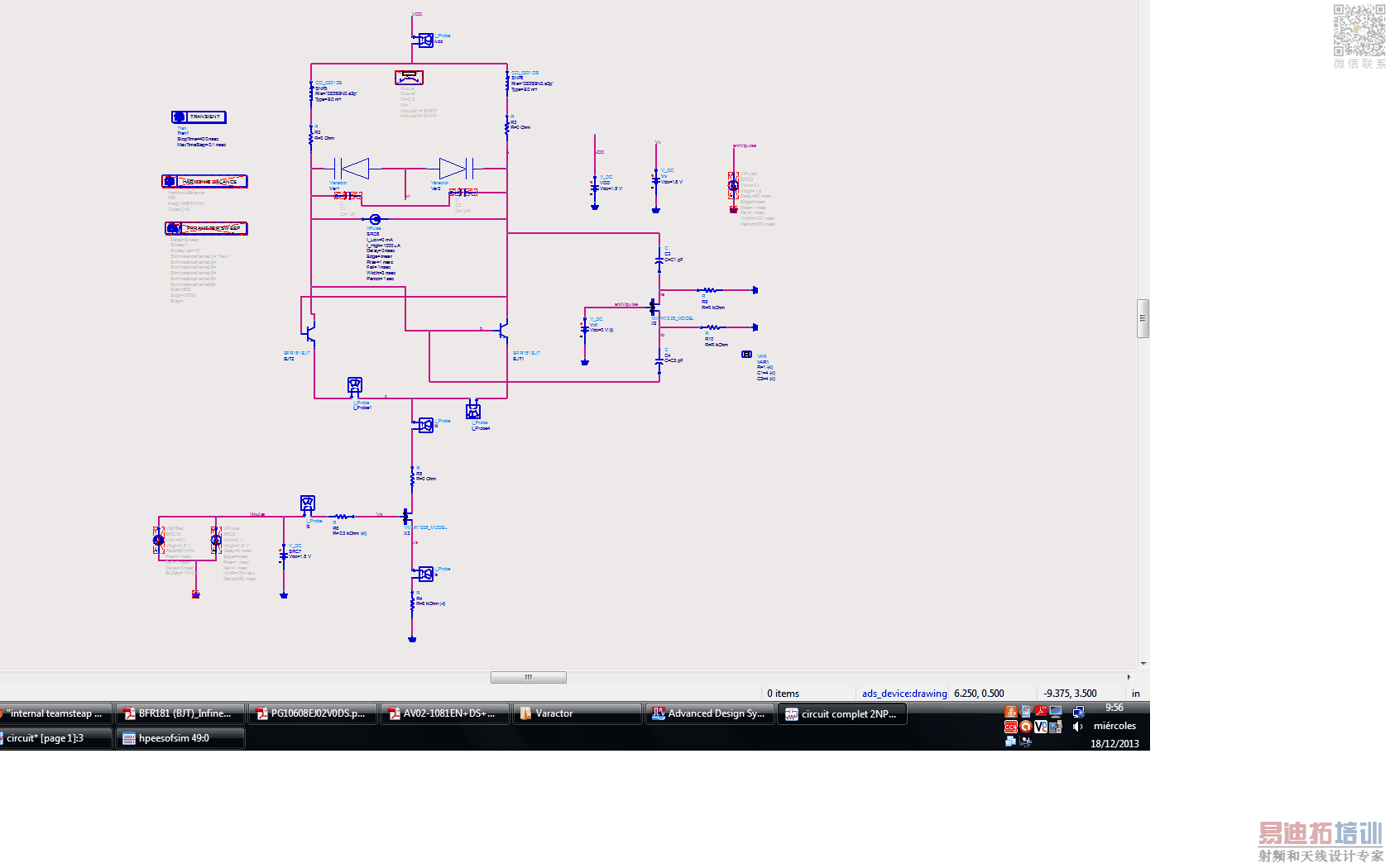
Hello and ty for your answers! I took a print of my circuit in .pdf format:
document1.pdf
I thought that this error appears when one of the variables of the circuit rise too fast, and it's probably what's going here. I don't think that I have a physical problem here but a simulator's one.
This is not happening only when i'm trying to use a pulse source. If I change the value of the bottom resistence from 8 to 7 maintaining the other variables constant I got this kind of error too. Am I doing something wrong? I'm quite new in this oscillator's world and I could make rookie mistakes.
Any tip will be aprreciated.
First question: why you use a E-PHEMT in the bottom current source, any reason, a paper? If you look at the dc-voltages at this transistor, VDS<1.1V, VG=1.8V, mhm? No idea if it's the problem, but maybe replace it with an ideal mos or bjt to examine roughly the dc-voltages.
...And why value of resistor is 8 kOhm? Maybe better to get smaller value of resistor and lowe gate voltage...
Please tell us WHEN exactly the error arises. In DC-simulation or in transient simulation. When it's in DC, try a test simulation with deactivated pulse current source.
Such circuits have always convergence errors.I have explained before in a different post:The simulators don't like uncertainties that include pulse generators,fast steeping square waves,switches,floating nodes,impacted transients etc.
The circuit should be nth order (Non)Linear Time Invariant as much as possible in time and frequency domain.Otherwise, you will see convergence errors again..
申明:网友回复良莠不齐,仅供参考。如需专业帮助,请学习易迪拓培训专家讲授的ADS视频培训课程。
上一篇:pin diode model ads
下一篇:MA46H071 Varactor model for ADS ?
ADS培训课程推荐详情>>
 国内最全面、最专业的Agilent ADS培训课程,可以帮助您从零开始,全面系统学习ADS设计应用【More..】
- Agilent ADS教学培训课程套装
- 两周学会ADS2011、ADS2013视频教程
- ADS2012、ADS2013射频电路设计详解
- ADS高低阻抗线微带滤波器设计培训教程
- ADS混频器仿真分析实例视频培训课程
- ADS Momentum电磁仿真设计视频课程
- ADS射频电路与通信系统设计高级培训
- ADS Layout和电磁仿真设计培训视频
- ADS Workspace and Simulators Training Course
- ADS Circuit Simulation Training Course
- ADS Layout and EM Simulation Training Course
- Agilent ADS 内部原版培训教材合集