- 易迪拓培训,专注于微波、射频、天线设计工程师的培养
How to extract RLC circuit from s-parameter touchstone file in ADS?
录入:edatop.com 点击:
Hi all,
I have a 1-port S-parameter touchstone file. I need to find the equivalent lumped RLC component of this file.
I have tried to use broadband Spice Model Generator in ADS, these output files(.dds,.bbn,.ckt,.hsp,.scs,.sp2,.sp3) have been generated.
Now, how can I use these file to obtain the schematic model of RLC circuit?
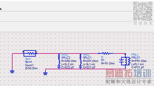
and the asummed circuit is:
I have a 1-port S-parameter touchstone file. I need to find the equivalent lumped RLC component of this file.
I have tried to use broadband Spice Model Generator in ADS, these output files(.dds,.bbn,.ckt,.hsp,.scs,.sp2,.sp3) have been generated.
Now, how can I use these file to obtain the schematic model of RLC circuit?
How ADS extract .s2p file from a 1-Port s-parameters ? I think yo do an error.
hi BigBoss,
I'm not familiar with broadband spice model but in the "Output Dialog" a "SPICE2" is selected, a <filename>.sp2 file is created not .s2p
which of these output file type can be used to extract RLC circuit? and how?
Thanks..
OK, I thought that you made a typo error.
You can use netlists which have been created by ADS by importing using with "Import design/Import Netlist" utility in ADS.It will import the netlist and create a schematic ( it may be very complex and weird..) with input port.Then you should create a symbol view for this "design". Then you can use it in your simulations.
Since the netlist is pretty complex, you may live convergence errors.
Single frequency / narrow band only, so that you have impedance value only?
Then simply use Y parameters (for parallel R||jX) or Z parameters for series R + jX.
Single frequency / narrow band only, so that you have impedance value only?
Then simply use Y parameters (for parallel R||jX) or Z parameters for series R + jX.
Thanks Volker..
but it's not single frequency, I worked on a large band of frequencies and I have the touchstone of Z and Y parameters at each frequency value.
This is sp2 file :
**************************************************
.SUBCKT bbs_sparametersfreq1_id_1_1 1 2
Rgs 1 2 3.21178412555915e+000
Rre1 1 10001 -3.25141268234100e+000
Lre1 10001 2 -3.32570684551416e-013
Rre2 1 10002 1.32608256557766e+002
Lre2 10002 2 5.41664111812668e-010
Rco3 1 13 3.19128906692906e+003
Lco3 13 23 -8.19926485701565e-008
Cco3 23 2 -5.38749572777799e-015
RGco3 23 2 -4.57767010301447e+003
Rre4 1 10004 1.87836201305677e-001
Lre4 10004 2 9.23523443580927e-008
Rre5 1 10005 3.30021131047513e+002
Lre5 10005 2 9.54345093467311e-008
.ENDS bbs_sparametersfreq1_id_1_1
**************************************************
and sp3 :
***************************************
*bbspice subcircuit with consecutive port numbers.
.SUBCKT bbspice_sparametersfreq1_subckt port_1 gnd_0
* PORT_1
vi_1 port_1 _net_1 0.00000000000000e+000
vb_1 _net_4 _net_5 0.00000000000000e+000
R_Z0_1 _net_1 _net_2 5.00000000000000e+001 NOISE=0
H_b_1 _net_2 gnd_0 vb_1 1.41421356237310e+001
E_v_1 _net_3 gnd_0 port_1 gnd_0 7.07106781186548e-002
H_i_1 _net_4 _net_3 vi_1 3.53553390593274e+000
G_D_1_1 _net_5 gnd_0 _net_5 gnd_0 -8.79282975440907e-001
G_C_1_1 _net_5 gnd_0 _net_6 gnd_0 -3.71792910157380e+008
G_C_1_2 _net_5 gnd_0 _net_7 gnd_0 -5.34341859606860e+008
G_C_1_3 _net_5 gnd_0 _net_8 gnd_0 -6.89200413767455e+012
G_C_1_4 _net_5 gnd_0 _net_9 gnd_0 7.98714888436042e+012
G_C_1_5 _net_5 gnd_0 _net_10 gnd_0 2.68409811859022e+008
G_C_1_6 _net_5 gnd_0 _net_11 gnd_0 -3.70944385851172e+008
* STATE_1
C_1 _net_6 gnd_0 1.00000000000000e-011
G_A_1_1 _net_6 gnd_0 _net_6 gnd_0 3.20885913557258e-003
G_B_1_1 _net_6 gnd_0 _net_4 gnd_0 -1.00000000000000e-011
* STATE_2
C_2 _net_7 gnd_0 1.00000000000000e-011
G_A_2_2 _net_7 gnd_0 _net_7 gnd_0 3.83413977446570e-002
G_B_2_1 _net_7 gnd_0 _net_4 gnd_0 -1.00000000000000e-011
* STATE_3
C_3 _net_8 gnd_0 1.00000000000000e-011
G_A_3_3 _net_8 gnd_0 _net_8 gnd_0 4.58635409177495e+000
G_B_3_1 _net_8 gnd_0 _net_4 gnd_0 -1.00000000000000e-011
* STATE_4
C_4 _net_9 gnd_0 1.00000000000000e-011
G_A_4_4 _net_9 gnd_0 _net_9 gnd_0 4.93557514785379e+000
G_B_4_1 _net_9 gnd_0 _net_4 gnd_0 -1.00000000000000e-011
* STATE_5
C_5 _net_10 gnd_0 1.00000000000000e-011
G_A_5_5 _net_10 gnd_0 _net_10 gnd_0 6.10707697118832e-003
G_A_5_6 _net_10 gnd_0 _net_11 gnd_0 -2.58783161282342e-001
G_B_5_1 _net_10 gnd_0 _net_4 gnd_0 -2.00000000000000e-011
* STATE_6
C_6 _net_11 gnd_0 1.00000000000000e-011
G_A_6_6 _net_11 gnd_0 _net_11 gnd_0 6.10707697118832e-003
G_A_6_5 _net_11 gnd_0 _net_10 gnd_0 2.58783161282342e-001
.ENDS bbspice_sparametersfreq1_subckt
***************************************
***************************************
* S-based subckt
*bbspice subcircuit with external port numbers.
.SUBCKT bbspice_sparametersfreq1 1 0
x_ 1 0 bbspice_sparametersfreq1_subckt
.ENDS bbspice_sparametersfreq1
***************************************
sp2 means SPICE 2G6 compatible circuit description. Did you ever look into a sp2 file if it contains only RLC elements and not e.g. transmission lines? If so, it can be directly sketched as lumped RLC circuit.
You may want to post an example of a generated sp2 or sp3 file.
The SPICE 2 circuit is using RLC elements only, but unfortunately some of it have negative value, in other words it's no physically plausible model. Don't know if the ADS generator can be forced to generate physical RLC models. I read that a similar Sonnet tool has the feature.
BB Spice Model Generator creates models based on rational equation model fitting not physical base.
There are many control sources, mutual couplings and negative capacitances and inductances are included.
So you can not realize them by actual components generally.
First, there are negative resistance in your "sp2".
So it can not be stable circuit.
You can force passivity in BB Spice Model Genetator.
Negative capacitance and inductance don't cause unstability of circuit.
Howerver negative resistance causes unstability of circuit.
Even if there are only positive resistances, capacitances and inductances in equivalent circuit, equivalent circuit could be unstable.
Summation of reactive energy has to be positive for passivity.
It could be negative by coupling coefficients even if there are only positive capacitances and inductances.
This reactive energy is evaluated by Capacitance matrix and Inductance matrix as quadratic form.
However even if you force passivity in BB Spice Model Genetator,
you can not realize them by actual components generally, since there many control sources, mutual couplings and negative capacitances and inductances are included.
Just there are no negative resistances at least.
And positive reactive energy is assured.
Assume RLC equivalents by physical insight for target DUT.
Them fit it to S-parameter by optimizer.
Thanks pancho_hideboo.
I did that. I assumed RLC circuit and put the goals but the graphic was fitted the expected value at the beginning of frequency range and the rest was too far away.
The art of parameter fitting is specifying an appropriate quality criterion and setting reasonable constraints that enforce e.g. an uniform distribution of pole frequencies.
Yes. I think that I have some mistakes in specifying the limits. Are there specific rules for determining the goals?
when I put the limitation in the range (4 GHz - 8 GHz), the optimization was correct but when I complete the limitation for the rest of frequencies the result was too far away
Why do you show nothing ?
This is true all through this thread.
Show us schematics or netlist and result graphs.
Curve fitting could succeed as far as equivalent circuit structure which you assume is enough reasonable for target DUT.
this is the required final result
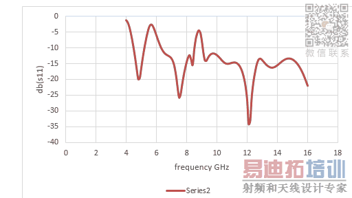
and the asummed circuit is:
This is not ADS graph.
Do you think there is anyone who can understand what you want to show ?
Do you show target db(s11) ?
Curve has to be constitute from two curves, target and fitted.
Show us schematics or netlist where optimizer setups are showed.
Results graphs which shows target and fitted results.
Followings are needed.
Smith chart plot.
Rectangular plot for db(s11) and phase(s11).
No. In broadband model extractions and similar methods that do not replicate the physical structure, negative elements are allowed in a branch model that is both passive and stable.
See https://www.sonnetsoftware.com/suppo...tSynthesis.pdf
@Mashna: I agree that a physics based model (educated guess) + parameter fitting is often the better approach. Especially if we can find good starting values by evaluating the S-params. Unfortunately your S-params look really complicated, so this will be a challenge. What is your DUT, is it electrically large so that we also need transmission line components (delay) in addition to the RLCG?
Wrong.
Constant negative resistance causes unstability, unless it is canceled.
It generates RHP(Right Half Plane) poles.
Even if RHP poles are canceled by RHP zeros, It results in blowup in Transient analysis.
This in "Internal Unstability" which is well known in Control System Theory.
On the other hand, there is no problem for AC or SP Analyses.
In oscillator, negative resistance can change its value during operation.
Just another way to say that a network with some negative resistance and reactance elements can be stable under circumstances.
You can check that it's the case for the spice circuits posted in #8.
Exactly that is where your first statement was wrong/incomplete: "unless it is cancelled". See IEEE MTT paper by IEEE fellow James Rautio that I linked above.
申明:网友回复良莠不齐,仅供参考。如需专业帮助,请学习易迪拓培训专家讲授的ADS视频培训课程。
上一篇:ADS and axial report
下一篇:PLL phase noise analysis in ADS
ADS培训课程推荐详情>>
 国内最全面、最专业的Agilent ADS培训课程,可以帮助您从零开始,全面系统学习ADS设计应用【More..】
- Agilent ADS教学培训课程套装
- 两周学会ADS2011、ADS2013视频教程
- ADS2012、ADS2013射频电路设计详解
- ADS高低阻抗线微带滤波器设计培训教程
- ADS混频器仿真分析实例视频培训课程
- ADS Momentum电磁仿真设计视频课程
- ADS射频电路与通信系统设计高级培训
- ADS Layout和电磁仿真设计培训视频
- ADS Workspace and Simulators Training Course
- ADS Circuit Simulation Training Course
- ADS Layout and EM Simulation Training Course
- Agilent ADS 内部原版培训教材合集