- 易迪拓培训,专注于微波、射频、天线设计工程师的培养
Distorted radiation pattern for antenna array in ADS
录入:edatop.com 点击:
Hi,
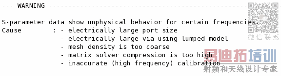
I am using ADS 2016 and to reduce the time taken for each simulation I have reduced the Mesh Density (cell/wavelength) to 5 and the solver compression level to "Reduced". Do these changes anyhow distort the radiation pattern I get as an outcome of my experiment?
I can observe from the figure below that I have grating lobes and to reduce them I need to lower or equal the inter element spacing to λ/2 mm. I am working with an inter-element spacing of 1.9 mm.
Is the problem below a problem with my design and concept or some issue with the software which I am not understanding?
I am attaching the file below.
Any sort of help will be much appreciated.

Why?
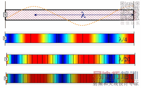
Mesh density controls the possible current distribution, and 5 cells per wavelength (with linear current gradient on each cell) is not enough to represent the correct physical currents flowing on your circuit.
A common default value is 20 cells/wavelength. For antennas where accuracy is not as critical, 10 cells/wavelength might be enough.
How critical is the effect of the solver compression level in the antenna simulations which I am performing?
I never changed that setting because my machine has 48GB anyway, but just looking at the setting now: is this really what you want? Doesn't reduced compression take more memory?
qthelp://ads.2016.01/doc/em/Defining_Solver_Settings.html
"Doesn't reduced compression take more memory"
I dont think so. may be the higher I go the more complicated its for the system to provide the performance. As if I set the solver compression level to normal the system always gives me this warning and I receive an error in performance.
申明:网友回复良莠不齐,仅供参考。如需专业帮助,请学习易迪拓培训专家讲授的ADS视频培训课程。
上一篇:How to include RF Transistor Vendor Kit in Advanced Designed Design(ADS)
下一篇:How to draw board outline in ADS?
ADS培训课程推荐详情>>
 国内最全面、最专业的Agilent ADS培训课程,可以帮助您从零开始,全面系统学习ADS设计应用【More..】
- Agilent ADS教学培训课程套装
- 两周学会ADS2011、ADS2013视频教程
- ADS2012、ADS2013射频电路设计详解
- ADS高低阻抗线微带滤波器设计培训教程
- ADS混频器仿真分析实例视频培训课程
- ADS Momentum电磁仿真设计视频课程
- ADS射频电路与通信系统设计高级培训
- ADS Layout和电磁仿真设计培训视频
- ADS Workspace and Simulators Training Course
- ADS Circuit Simulation Training Course
- ADS Layout and EM Simulation Training Course
- Agilent ADS 内部原版培训教材合集