- 易迪拓培训,专注于微波、射频、天线设计工程师的培养
首页 > ADS > ADS FAQ > [ADS] Need urgent help regarding ADS. getting irregular results in S(1,1) parameters
[ADS] Need urgent help regarding ADS. getting irregular results in S(1,1) parameters
录入:edatop.com 点击:
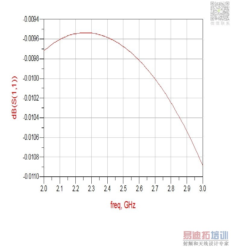
hi, i made a rectifier circuit in ads, and simulate it but my results of S(1,1) parameters are not coming good i-e the waveform is not below -10dB.
I have attached the screenshots of my circuit and result, can anybody detect the problem?
thankyou
I have attached the screenshots of my circuit and result, can anybody detect the problem?
thankyou

"S-parameters are small signal quantities and and they are simulated with small signal equivalent circuits so they are not related to applied signal strength"
First, -30dBm is too low to activate the diodes so the circuit won't work.Diodes' turn-on values are 0.2-0.85V depending on diodes..Your voltage is 7.07mV if the source is terminated with pure 50 Ohm.
Second, s-parameters are not suitable for this kind of circuits.They are small signal parameters and all components are linearized around OP,So OP is zero, s-parameters faulty..
Third, LSSP should be used for large signal applied circuits or HB can also be used.
Transient simulation is better to observe the eventments on every net and node..
[QUOTE=BigBoss;1420346]"S-parameters are small signal quantities and and they are simulated with small signal equivalent circuits so they are not related to applied signal strength"..
hey BigBoss thanks for the reply, i found it useful, but one more question viz, i was finding the input imepedance of the circuit through S- parameters then doing matching with input source, now that u say that S- parameters are not suitable in this circuit, then what should i do to find the impedance of the load i-e diode, capacitor and resistor in parallel? and what is OP and how did you find the voltage at the diode?
will be waiting for your reply. Thanks.
[QUOTE=Fairy&cutie;1420859]The input impedance of this circuit is totally bias depended so OP of the diodes is changing with signal amplitude and this is a large amplitude therefore while s-parameters are valid for single OP they are not valid anymore for other OPs.That's why I say you " use transient or HB method".
Impedance matching is not necessary in this case because impedance is variable with OP.The most important here is to have a proper driver circuit that is able to drive this level properly to the diodes.
ok. to get the things clear, i must tell you what this circuit actually is. basically it is a rectifier circuit which is rectifying an input signal of 2.45GHz frequency. now i can attach a bandpass filter after the source which will eliminate all the frequencies other than 2.45GHz, then a diode, a capacitor and a load resister in parallel.
now dont you think that there MUST be some matching circuit b/w bpf and diode/RC?
plus, why LSSP? i dont think that this circuit is getting large signal strength?
申明:网友回复良莠不齐,仅供参考。如需专业帮助,请学习易迪拓培训专家讲授的ADS视频培训课程。
上一篇:Error in EM simulation in ADS
下一篇:[ADS SNP File] Why Am I not getting the correct S-parameters ?
ADS培训课程推荐详情>>
 国内最全面、最专业的Agilent ADS培训课程,可以帮助您从零开始,全面系统学习ADS设计应用【More..】
- Agilent ADS教学培训课程套装
- 两周学会ADS2011、ADS2013视频教程
- ADS2012、ADS2013射频电路设计详解
- ADS高低阻抗线微带滤波器设计培训教程
- ADS混频器仿真分析实例视频培训课程
- ADS Momentum电磁仿真设计视频课程
- ADS射频电路与通信系统设计高级培训
- ADS Layout和电磁仿真设计培训视频
- ADS Workspace and Simulators Training Course
- ADS Circuit Simulation Training Course
- ADS Layout and EM Simulation Training Course
- Agilent ADS 内部原版培训教材合集