- 易迪拓培训,专注于微波、射频、天线设计工程师的培养
Momentum vs FEM: what's the problem ?
Hello,
I would like to apologize for this question since I amquiteit's a recurring question...
Idesign an antenna (J-dipole) using Momentum: results are great...
However, I would like to check the simulation with FEM to take account of finite FR4 substrate...
1) with the default options, results with FEM are odd: the question is how to set the FEM properly? I read from documentation and it is not very clear...
2) one FEM siting will work, how to "cut" the substrate ?With 3D visualisation tool, the FR4 layer is always the same size of simulation_box...
Thanks for your reply.
F.
附图/附件

J-dipole.png

Antenna_FEM.png

Antenna_Momentum.png
Have you set enough spacing to the simulation boundary, and open boundaries?
I think you can use the "boundary area layer" setting to specify a layer that determines the substrate boundary for FEM.
Myself, I use this method: For finite dielectrics, I specify air for the base dielectric at that layer, and insert a dielectric via that represents the PCB material.
Thank you very much for your answer: boundary area layermakes the difference.
However, how to improve the solution ?
Is the difference between two simulations comes really from the finite substrate ?
Or I miss something in the definition of port or in FEM options ?
I put my files.
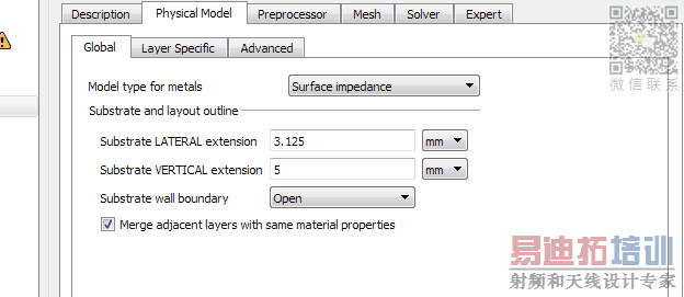
About FEM: your can see what I change.
The only other change is the convergence: I put 2 for "Consecutive passes of delta error required"
Any suggestions for improvements ?
(I am little bit surprise by the difference...
Thanks a lot
F.
FEM


MoM


I can't see this from your screenshot: What is the boundary type and boundary distance on the side with the port?
I would prefer to have an absorbing boundary there, and use an internal lumped port for the feed. Distance to the absorbing boundary at least 1/4 wavelength on all sides.
For the "Consecutive passes of delta error required", I usually use 3 to make sure the algorithm has converged and donesn't stop too early at a local minimum.
Hello,
I tried to answer you on Keysight forum, however, it doesn’t work… We have some problems with our network…
So I answer below with new questions.
Thanks for your time.
François
-
François Boone, ing., Ph. D.
Professeur,
Directeur du département de génie électrique et de génie informatique
Université de Sherbrooke
2500, boul. de l'Université
Tél. : 819 821 8000 poste 65900
Fax : 819 821 7937
Courriel : <mailto:>
www.usherbrooke.ca/genie<http://www.usherbrooke.ca/genie:http://www.usherbrooke.ca/genie>
Le 18 août 2018 à 08:07, volker_muehlhaus <<mailto:>> a écrit :
Keysight Community
Re: Momentum vs FEM: what's the problem ?
reply from volker_muehlhaus in EDA Software - View the full discussion
I can't see this from your screenshot: What is the boundary type and boundary distance on the side with the port?
Boundary type: open (I suppose it’s equivalent to absorbing boundary since the other choices are PEC or PMC.
I would prefer to have an absorbing boundary there, and use an internal lumped port for the feed. Distance to the absorbing boundary at least 1/4 wavelength on all sides.
I used 25mm on all sides and decide to increase this distance to 50 millimeterI work around 2.4 GHz: let’s say 3 GHz: the free space lambda is then 100mm and the guided lambda < free space lambda.
For the "Consecutive passes of delta error required", I usually use 3 to make sure the algorithm has converged and donesn't stop to early at a local minimum.
Thanks for this advice.
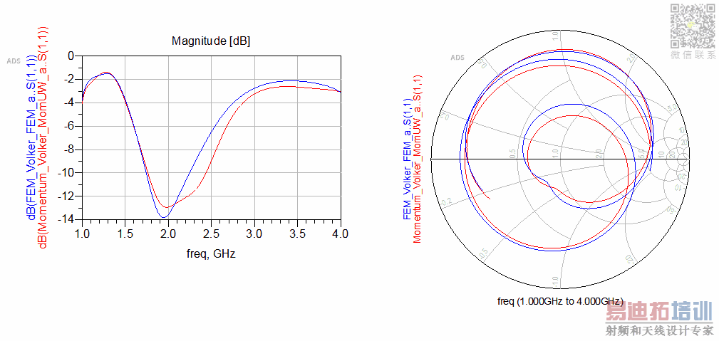
As you can see in FEM-MoM-Results.png file, I made different simulations with previous parameters.
You speak about internal lumped port… Since I have the choice between auto or direct port, I assume that these are lumped ports: the two cases give the same result, the blue curve… I don’t trust this result since the design isn't done for resonant antenna (very small bandwidth).
If I use wave port with TML, zero length, I obtain pink or fuchsia curve: It is a little bit better but not like MoM results.
I check about port: I attach the file 3D-port1.png: I am a little bit surprise by the shape of this port: It seems to me that the shape have to be rectangular, just below micro strip line…
But it is not the case and I didn’t find any way to change the shape.
Thank you very much if you can give me more advice.
Best regards.
François
Reply to this message by replying to this email, or go to the message on Keysight Community
Start a new discussion in EDA Software by email or at Keysight Community
Following Re: Momentum vs FEM: what's the problem ? in these streams: Inbox
This email was sent by Keysight Community because you are a registered user.
You may unsubscribe instantly from Keysight Community, or adjust email frequency in your email preferences
附图/附件

3D.png

3D-port1.png

FEM-MoM-Results.png
Hello François,
you have one edge where both signal and ground line end, and it seems that ADS uses the entire edge length of the ground plane for the port reference width (instead of just a part of the edge underneath the signal line). In Momentum that causes trouble, in FEM I don't know. Can you create an archived ADS project with this antenna and upload it here?
Best regards
Volker
Ce message vous est transmis par François Boone à l'aide du service d'envoi de
fichiers de l'Université de Sherbrooke.
Numéro de suivi:624fab0464
Sujet : Re: - Re: Momentum vs FEM: what's the problem ?
Message : You can download the archive of the project. Best regards.
Télécharger les fichiers
Nombre de fichiers disponibles: 1
Expiration: 2018-08-24
Lien: https://www.usherbrooke.ca/envoi-de-fichiers/index.php%3Ftoken%3D624fab0464%26key%3D12017deb254ed40ac51b23ce6c4ece6471ee8702:https://www.usherbrooke.ca/envoi-de-fichiers/index.php?token=624fab0464&key=12017deb254ed40ac51b23ce6c4ece6471ee8702
Hello Volker,
My archive is more than 170Mo.
So I use the unit ersatz system to send you the 7zads file.
Best regards
François
-
François Boone, ing., Ph. D.
Professeur,
Directeur du département de génie électrique et de génie informatique
Université de Sherbrooke
2500, boul. de l'Université
Tél. : 819 821 8000 poste 65900
Fax : 819 821 7937
Courriel :
www.usherbrooke.ca/genie
Le 21 août 2018 à 02:16, volker_muehlhaus <> a écrit :
Keysight Community
Re: Momentum vs FEM: what's the problem ?
reply from volker_muehlhaus in EDA Software - View the full discussion
Hello François,
you have one edge where both signal and ground line end, and it seems that ADS uses the entire edge length of the ground plane for the port reference width (instead of just a part of the edge underneath the signal line). In Momentum that causes trouble, in FEM I don't know. Can you create an archived ADS project with this antenna and upload it here?
Best regards
Volker
Reply to this message by replying to this email, or go to the message on Keysight Community
Start a new discussion in EDA Software by email or at Keysight Community
Following Re: Momentum vs FEM: what's the problem ? in these streams: Inbox
This email was sent by Keysight Community because you are a registered user.
You may unsubscribe instantly from Keysight Community, or adjust email frequency in your email preferences
>
Hello Francois,
thanks, I received your workspace and made some changes to the models.
- For Momentum, in emSetup I changed the physical model to 3D, so that it uses thick metal modelling instead of infinitely thin sheets.
- I changed the ground pin to an "edge/area pin" to make sure it doesn't extend across the entire edge.
- I didn't use any port calibration, because I don't trust that for this explicit ground case (my personal view, might be wrong).
- For FEM settings, I started from scratch. Frequency for mesh = 2GHz (instead of fmax), boundary distance 40mm.
I get rather similar results from Momentum and FEM now, which are somewhat different from yours.
There is one warning on my port in FEM that I don't understand, maybe that is something for Keysight support.
The packed project with my models is here:
http://muehlhaus.com/wp-content/uploads/2018/08/Type_6_volker_wrk.zip:http://muehlhaus.com/wp-content/uploads/2018/08/Type_6_volker_wrk.zip
Best regards
Volker
Thank you very much for your reply.
I will study carefully your projet to be able to obtain same results as you: a quick test gives similar results but with a difference about 1 dB compare to yours.
Best regards.
François
-
François Boone, ing., Ph. D.
Professeur,
Directeur du département de génie électrique et de génie informatique
Université de Sherbrooke
2500, boul. de l'Université
Tél. : 819 821 8000 poste 65900
Fax : 819 821 7937
Courriel :
www.usherbrooke.ca/genie
Le 21 août 2018 à 14:01, volker_muehlhaus <> a écrit :
Keysight Community
Re: Momentum vs FEM: what's the problem ?
reply from volker_muehlhaus in EDA Software - View the full discussion
Hello Francois,
thanks, I received your workspace and made some changes to the models.
- For Momentum, in emSetup I changed the physical model to 3D, so that it uses thick metal modelling instead of infinitely thin sheets.
- I changed the ground pin to an "edge/area pin" to make sure it doesn't extend across the entire edge.
- I didn't use any port calibration, because I don't trust that for this explicit ground case (my personal view, might be wrong).
- For FEM settings, I started from scratch. Frequency for mesh = 2GHz (instead of fmax), boundary distance 40mm.
I get rather similar results from Momentum and FEM now, which are somewhat different from yours.
There is one warning on my port in FEM that I don't understand, maybe that is something for Keysight support.
The packed project with my models is here:
http://muehlhaus.com/wp-content/uploads/2018/08/Type_6_volker_wrk.zip:http://muehlhaus.com/wp-content/uploads/2018/08/Type_6_volker_wrk.zip
Best regards
Volker
https://community.keysight.com/servlet/JiveServlet/downloadImage/2-87132-157856/mom_fem.PNG
Reply to this message by replying to this email, or go to the message on Keysight Community
Start a new discussion in EDA Software by email or at Keysight Community
Following Re: Momentum vs FEM: what's the problem ? in these streams: Inbox
This email was sent by Keysight Community because you are a registered user.
You may unsubscribe instantly from Keysight Community, or adjust email frequency in your email preferences
>
The workspace you created is very helpful.
I have generated the 3D view of your FEM design and found that due to the internal area port, the impedance line is slightly slanted like the following picture.
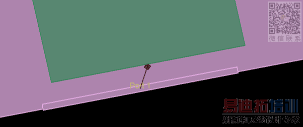
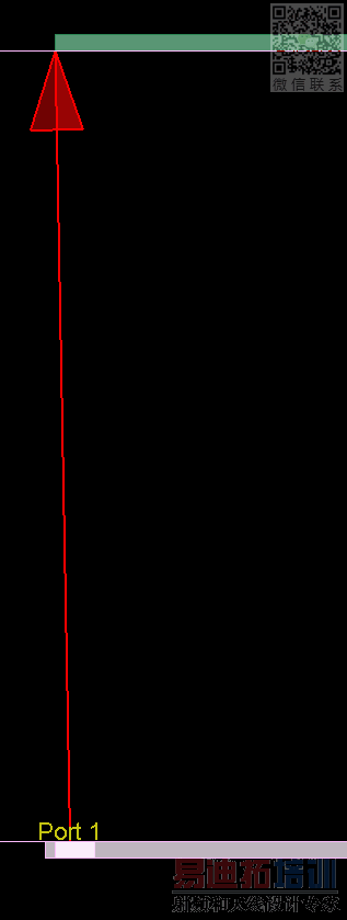
It is generating the following warning
--- WARNING -------------------------------------------------------------------
Port P1 has one pin with a segment and one pin without a segment. This may result in a triangular sheet port. Use an Edge/Area pin to associate a line segment with the negative pin to adjust the shape of the port.
-------------------------------------------------------------------------------
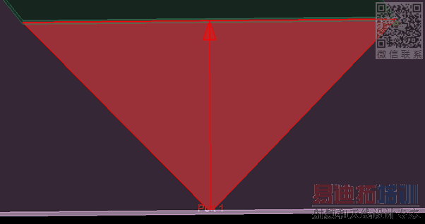
=============================================================
I changed the area ground pin to edge pin where the edge length is equal to the width of the top plane microstrip (here it is 3.18 mm) and the edge pin is connected exactly in the same X-Y location/co-ordinate of the + pin. This removes the triangular sheet port warning.
If I use uncalibrated (Direct) edge port I get the rectangular shaped port like the following
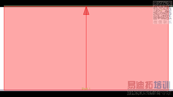
Now, for TML case, the waveport extends below the ground plane like following. Is the shape of the waveport corrector it needs to be re-sized? How can it be re-sized so that it can't go below the ground plane?
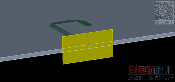
I observed dissimilarity in the results between this extended calibrated TML waveportand uncalibrated Direct port.
申明:网友回复良莠不齐,仅供参考。如需专业帮助,请学习易迪拓培训专家讲授的ADS视频培训课程。
上一篇:Unable to access library: ckt
下一篇:Smith Chart Matching component is missing in the ADS 2019
 国内最全面、最专业的Agilent ADS培训课程,可以帮助您从零开始,全面系统学习ADS设计应用【More..】
- Agilent ADS教学培训课程套装
- 两周学会ADS2011、ADS2013视频教程
- ADS2012、ADS2013射频电路设计详解
- ADS高低阻抗线微带滤波器设计培训教程
- ADS混频器仿真分析实例视频培训课程
- ADS Momentum电磁仿真设计视频课程
- ADS射频电路与通信系统设计高级培训
- ADS Layout和电磁仿真设计培训视频
- ADS Workspace and Simulators Training Course
- ADS Circuit Simulation Training Course
- ADS Layout and EM Simulation Training Course
- Agilent ADS 内部原版培训教材合集

