- 易迪拓培训,专注于微波、射频、天线设计工程师的培养
为5G通信做准备,一种设计具有宽波束覆盖的毫米波相控阵天线设计方法
录入:edatop.com 点击:
Millimeter-Wave Phased Array Antenna with Wide Beam Coverage
I. Introduction
Mobile communication devices are indispensible for our daily life and the number of the devices is explosively increased, which is demanding large data traffic in wireless communications. Researchers have studied to develop various wireless technologies to meet the demand. Recently, the millimeter wave frequency bands, 3 and 300 GHz have been paid attention to future wireless communications, since a large bandwidth is allowable for supporting a high data rate. A 28 GHz frequency band has been exploited for the next generation (5G) mobile cellular communication systems, and indoor and outdoor test results showed the feasibility of the mm-wave band for the mobile cellular communications [1] [2].
There are many challenges to be addressed for the usage of the mm-wave band for the mobile communications, however, since the mm-wave band experiences severe propagation loss compared with the frequency bands for the current cellular systems. In cellular systems, mobile devices are placed at any place and any position regarding to base stations. Thus, mobile devices for the 3/4G cellular systems have omni-directional antennas which are easily implemented for that frequency bands with high SNR (signal-to-noise ratio). Omni-directional antennas are not applicable for the mm-wave cellular systems due to high propagation loss causing not high enough SNR. A phased array antenna and beamforming techniques which could steer its beam to cover the entire space must be employed to achieve high SNR for the mm-wave cellular systems. However, in a realistic implementation of mm-wave mobile devices, the isotropic-like array element for wide beam coverage is almost unobtainable. Not only that, the number of paths, each with phase shifting block, is limited by some issues concerning requirements for power consumption or space occupied by them. Some studies have demonstrated phased array antennas for the 28 GHz frequency bands in the applications of mobile devices in the form of substrate integrated antennas [3]- [5].
In this letter, a mm-wave beam steerable 1ⅹ4 planar monopole array antenna embedded in a dielectric substrate for a 28 GHz RF test platform is demonstrated with a wide beam coverage.
II. Array Antenna Design and Measured Results
A. Array Antenna Design
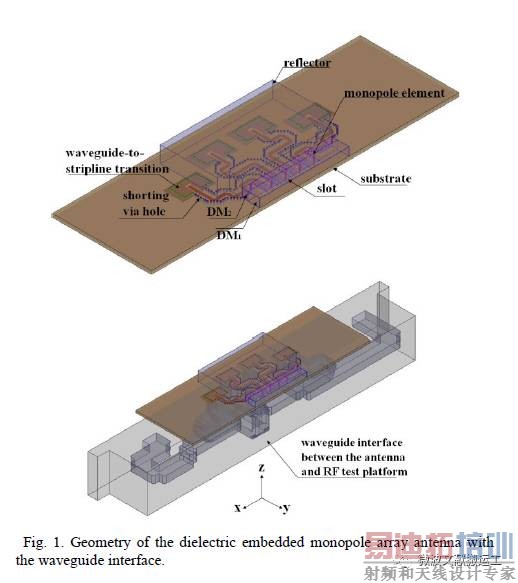
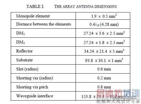
A vertical monopole array antenna embedded in a dielectric material has been designed as shown in Fig. 1. The rectangular metal strips are embedded between two dielectric materials, DM1 and DM2. The DM1 is a Teflon with a relative permittivity of εr = 2.1 and the DM2 is a Taconic TLY with εr = 2.2. A metal structure, reflector stands behind the DM2 and is shorted to the ground. The widths of DM1 and DM2 are λ/2 and λ/4, respectively, where λ is the wavelength in the dielectric material. A feed network is developed using stripline transmission lines and the substrate of the stripline is a Taconic TLY with εr =2.2. There are slots on the top ground plane of the substrate to connect the striplines with the metal strips using vias. For each stripline, shorting vias are also developed with the width of λ/2. The array antenna dimensions are listed in Table I. Note that λ0 is the wavelength of the free-space.
B. Waveguide-to-Stripline Transitions
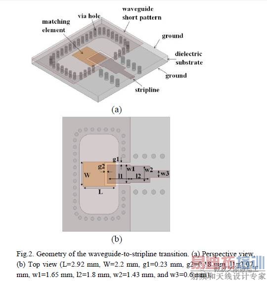
The 28 GHz RF test platform for the array antenna has waveguides at RF front ends and the array antenna has a feeding network of striplines. Thus, a waveguide-to-stripline transition has been developed to connect each other in a planar form [6] [7]. The geometry of the waveguide-to-stripline transition is shown in Fig. 2. A Taconic TLY with εr = 2.2 and tanσ=0.009 of thickness of 1 mm is used as a dielectric substrate. On the bottom ground plane, there is an opening with the same size with the aperture size of the waveguide (WR-28). A coupling patch is patterned on the bottom ground plane. A waveguide short pattern is printed on the same plane with the stripline and electrically shorted to the top and bottom ground planes through the surrounding vias. The width of the stripline is 0.78 mm corresponding to 50 ohm of the characteristic impedance and the stripline is inset into the waveguide short pattern. As for the simulated results, the waveguide-to-stripline transition has a return loss of <-20 dB and an insertion loss of <0.15 dB for the frequency band of 27.5 – 28.5 GHz. Note that the dielectric loss and conduction loss with a finite conductivity of σ=5.8ⅹ107 S/m of a copper clad were included in the simulations.
C. Results
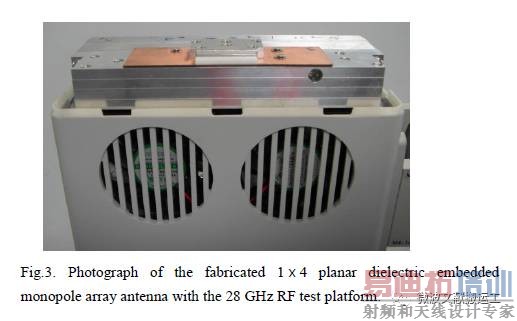
The proposed 1ⅹ4 planar dielectric embedded monopole array antenna was fabricated and installed on the top of the 28 GHz RF test platform as shown in Fig. 3. The radiation patterns of the array antenna were measured in an anechoic chamber. The RF test plat form was not installed in the chamber and a power divider with the insertion loss of 10.5 dB was connected to the array antenna to feed in-phased signals to each port of the array antenna for the pattern measurements. The simulated and measured results of the radiation patterns of the array antenna are shown in Fig. 4. The peak gain of 10 dBi is measured at (
Φ=90°, θ=81°). Note that the peak gain is observed at an elevated plane, not the horizontal plane ( θ=90°). The 3-dB beam width for the E-plane is 90°. For the H-plane, the 3-dB beam width is 30° and the SLL (side-lobe level) is -10 dB.
The simulated scanning performance in the H-plane of the array antenna at 27.925 GHz is shown in Fig. 5. The developed 28 GHz RF test platform supports 8 beams for a beam forming. Thus, the proposed array antenna was simulated for the 8 main beams to be directed as Φ=±5°, ±25°, ±45°, and ±75° as shown in Fig. 5. Note that the beams for ±45° and ±75° are almost overlapped. Taking into account 3-dB beam width, the proposed array antenna can steer from -90° to +90°, which is wide beam coverage for the planar array antenna. To measure the scan performance, the array antenna was installed on the top of the 28 GHz RF test platform through the WR-28 waveguides and rotated on a turn-table. The measured results of the scan performance in the H-plane of the array antenna at 27.925 GHz are shown in Fig. 6. As similar with the simulated results, the measured scan range of the array antenna is achieved to cover from -90° to +90° with the 3-dB beam width. The SLL is approximately -10 dB.
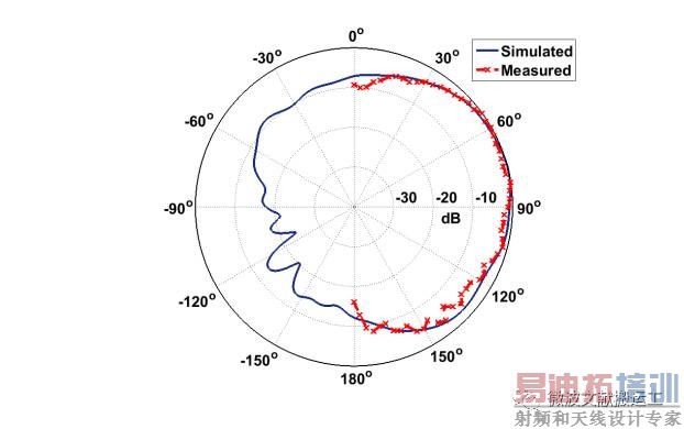
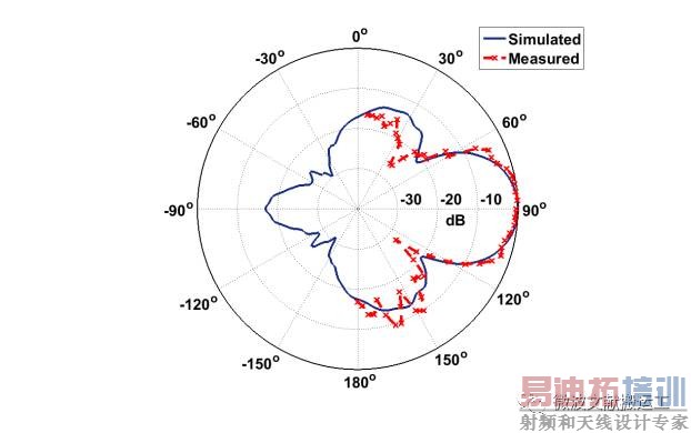
Fig.4. Simulated and measured radiation patterns for the planar 1ⅹ4 dielectric embedded monopole array antenna at 27.925 GHz. (a) E-plane (yz-plane), (b) H-plane (xy-plane).

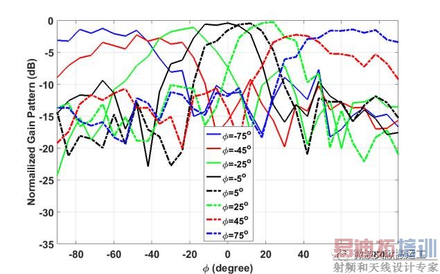
Fig.6. Measured scanning performance in the H-plane of the 1ⅹ4 planar dielectric embedded monopole array antenna at 27.925 GHz.
III. Conclusion
The design and experimental results of a mm-wave beam steerable 1ⅹ4 planar dielectric embedded monopole array antenna for a 28 GHz RF test platform has been presented. The scanning performance of the array antenna with the RF test platform was measured. The measured results show that the proposed array antenna can provide wide beam coverage from -90° to 90° taking account of the 3-dB beam width.
=============================================================
本着知识分享精神,如涉及到版权事宜请立即联系我们处理,如有冒犯,敬请谅解!更多文献信息获取请关注
上一篇:挑战iPhone
7?
乐2s
Pro天线设计又有创新
下一篇:大牛教你绕过智能硬件设计的那些坑——天线设计、工业设计