- 易迪拓培训,专注于微波、射频、天线设计工程师的培养
SAM Phantom with Helix Antenna - CST2013 MWS Examples

General Description
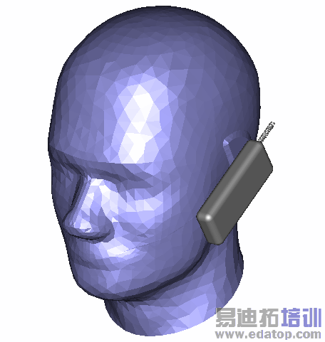
This example demonstrates the capability of the multilevel subgridding scheme. The EN 50361 SAM Phantom head (SAM = "Specific Anthropomorphic Mannequin") is used together with a simplified mobile phone with a small helix antenna. If subgridding is applied the number of mesh cells for this structure could be reduced significantly and in consequence the overall simulation runs more than ten times faster.
Note:
The SAM Phantom head has been facetted to reduce memory requirement and CAD model complexity in this example. A smooth version is included in the SAR Head & Hand - Mobile Phone example. A more detailed human model voxel data set is also available. Please contact CST support for further information.
Structure Generation
The phantom head is imported from a SAT file and is modelled by a shell filled with a liquid which represents the average material properties of the head. The working plane is set to the left hand side of the head in order to define the simplified cell phone model.
In order to obtain a fine mesh resolution of the helix antenna a local maximum mesh step is defined for this solid. Activating subgridding will keep this mesh refinement while other parts of the calculation domain are coarsened due to their wavelength resolution.
Solver Setup
To start the transient solver, an excitation source has to be defined. The excitation of the cell phone model is done by a discrete element between the helix antenna and the main body. For post processing investigations a farfield monitor and a power loss density monitor for SAR calculations are defined.
By default the transient solver calculates different subgrid levels with different time steps in order to obtain further speed-up of the simulation.
Post Processing
Using the excitation of the discrete port the resulting time signals are automatically converted into the corresponding scattering parameters. They are listed in the navigation tree in the folder 1D Results.
The SAR calculation is based on the power loss density monitor. It can be started through the Post Processing: 2D/3D Field Post Processing  SAR
SAR  dialog box or by setting up a post processing template in Post Processing: Result Templates
  Template Based Postprocessing
  which will be executed automatically after the solver run. After the SAR calculations are finished, the results are accessible via the folder 2D/3D Results
  SAR in the navigation tree.
The directivity or other farfield parameters can also be investigated in the navigation tree in the folder Farfields.
CST微波工作室培训课程套装,专家讲解,视频教学,帮助您快速学习掌握CST设计应用
上一篇: Microstrip Radial Stub - CST2013 MWS Examples
下一篇: Planar Antenna (Mobile phone) - CST2013 MWS Examples
 最全面、最专业的CST微波工作室视频培训课程,可以帮助您从零开始,全面系统学习CST的设计应用【More..】
频道总排行
- Rectangular Waveguide Tutorial
- FSS: Simulation of Resonator
- CST2013 MWS Examples: Thermal C
- Dipole Antenna Array - CST201
- CST MWS Examples - CST2013 M
- Microstrip Radial Stub - CST2
- Dielectric Resonator Antenna -
- Interdigital Capacitor - CST20
- CST2013 MWS Examples: Biological
- Lossy Loaded Waveguide - CST2
