- 易迪拓培训,专注于微波、射频、天线设计工程师的培养
FSS: Simulation of Resonator Array - CST2013 MWS Examples
录入:edatop.com 点击:
Abstract
A Frequency Selective Surface (FSS) is a periodic assembly of one- or two-dimensional resonant structures, either as apertures in a thin conducting sheet or as metallic patches on a substrate, which may have a band-pass or band-stop function respectively. The increasing interest within the high-frequency community in this sort of structure has also made its accurate simulation increasingly important. This tutorial describes how an FSS structure may be simulated efficiently using CST MICROWAVE STUDIO (CST MWS). A simple unit cell of a ring resonator band-stop infinite array is considered as an example.
Contents
Introduction
Physical description
Frequency selective surfaces are increasingly used for the frequency filtering of plane waves in radar or communications systems. A one- or two-dimensional periodic array of resonant structures on a backing material, either apertures in a metallic sheet or metallic patches on a substrate, acts as a filter for a plane wave arriving from any angle of incidence. In this example an array of full wavelength resonant conducting rings on a dielectric substrate is simulated. Since the FSS would be used on curved structures like radomes, it is desirable that the FSS have the same resonant frequency for all incident plane wave angles. For a given polarisation, ring resonators are known to be stable with the scan angle. CST MICROWAVE STUDIO (CST MWS) can be used to establish the angular dependence of the resonant frequency.
CST MICROWAVE STUDIO? Model: Parameter definition and preliminary settings
The simulation of an entire array of resonant rings would be prohibitively time and memory consuming. The use of CST MWS’s unit cell boundary conditions in the directions of periodicity allows a rapid but no less accurate simulation of large surfaces. Setting up the simulation may be greatly eased by using the ”FSS - Unit Cell (FD)” template, which automatically applies unit cell boundary conditions in the x- and y-directions and sets up Floquet port excitations in the positive and negative z-directions. There is no need to define master and slave boundary conditions; the phase relation of the opposing boundaries is automatically set by specifying the incident angle of the inward travelling plane wave.
o Create a New Project
After launching the CST STUDIO SUITE you will enter the start screen showing you a list of recently opened projects and allowing you to specify the application which suits your requirements best. The easiest way to get started is to configure a project template which defines the basic settings that are meaningful for your typical application. Therefore click on the Create Project button  in the New Project section.
Next you should choose the application area, which is Microwaves & RF for the example in this tutorial and then select the workflow by double-clicking on the corresponding entry.

For the frequency selective surface, please select Periodic Structures  FSS, Metamaterial - Unit cell Frequency Domain Solver
  .
.
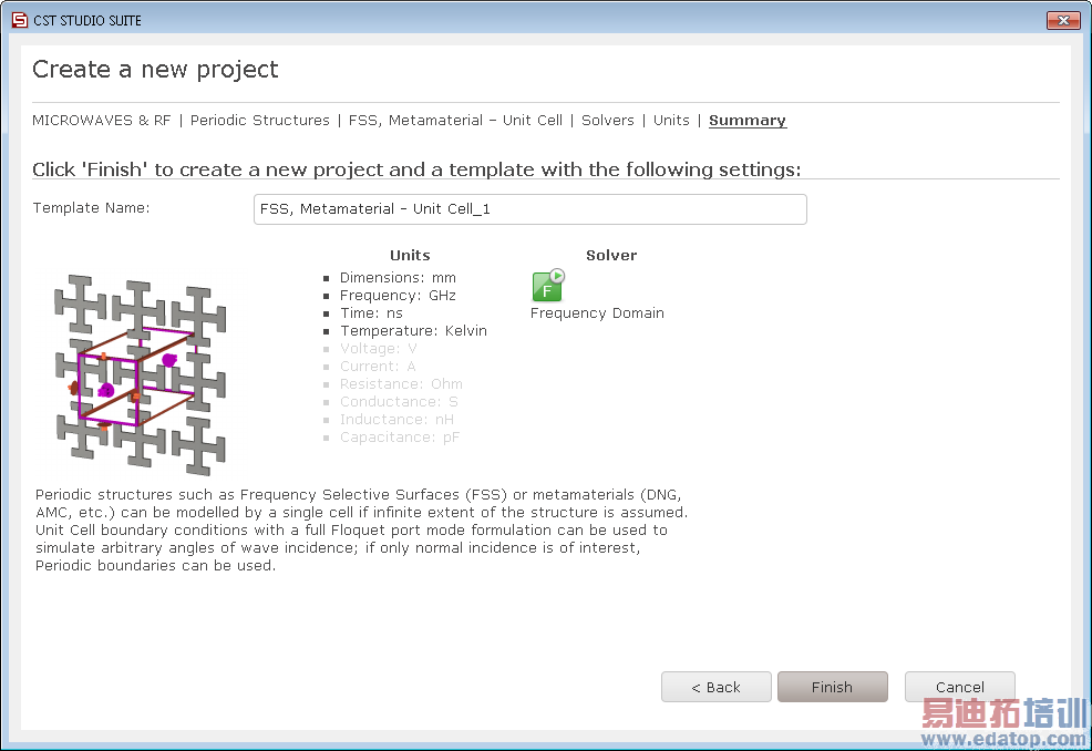
At last you are requested to select the units which fit your application best. For the frequency selective surface, please leave the settings as follows:
Dimensions: | mm |
Frequency: | GHz |
For the specific application in this tutorial the other settings can be left unchanged. After clicking the Next button, you can give the project template a name and review a summary of your initial settings:
Finally click the Finish button to save the project template and to create a new project with appropriate settings. CST MICROWAVE STUDIO will be launched automatically due to the choice of the application area Microwaves & RF.
o Create structure
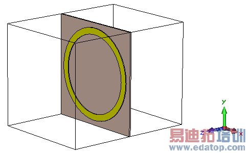
It is only necessary to construct a single ring on its backing substrate. Construction of the geometry itself is simple: a substrate is defined using a brick primitive object, and then a hollow cylinder can be used to create the ring. The conducting ring is a ”lossy metal” type copper, and the substrate is Arlon AD 300 with a relative permittivity of 3.
The incident angle of the incoming plane wave may be specified by setting angles Theta and Phi, both of which have already been parameterized by the template. The periodicity of the FSS is also freely configurable as shown below. Different periodicities can be assigned in the x- and y-directions, and the use of a skewed lattice is also possible by specifying the grid angle (this can be useful for simulating compact closely coupled arrays).
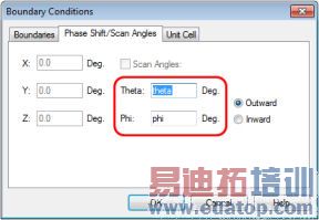
The incident plane wave angle and unit cell periodicity of the FSS are freely configurable.
For off-normal incident angles the Floquet port modes ensure that the reflected wave is recorded in the direction of optical reflection, while the transmission is in the same direction as the incident wave. This is elucidated by the figure below.
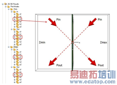
Incident and transmitted directions are automatically set by the Floquet modes.
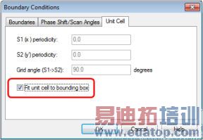
The periodicity can also be specified, as in this example, by setting the size of the substrate to the desired periodicity, then checking the Fit unit cell to bounding box checkbox.

Unit cell boundary conditions can be set to fit the bounding box.
The default Floquet port settings excite two plane waves with orthogonal electric fields as shown below (TE(0,0) and TM(0,0) modes), but higher order modes may also be specified in the port properties dialog (Details). Co-polar and cross-polar coupling between the modes, both reflection and transmission, are represented in terms of S-parameters. The co-polarised reflection of mode 1 at port Zmin would thus, for example, be named SZmin(1),Zmin(1), and the cross-polarised transmission between modes 2 and 1 SZmax(1),Zmin(2).
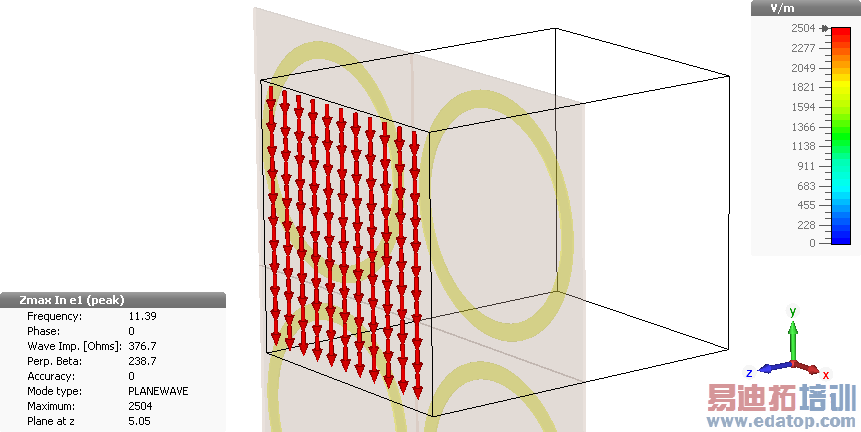
TE(0,0) mode, electric field.
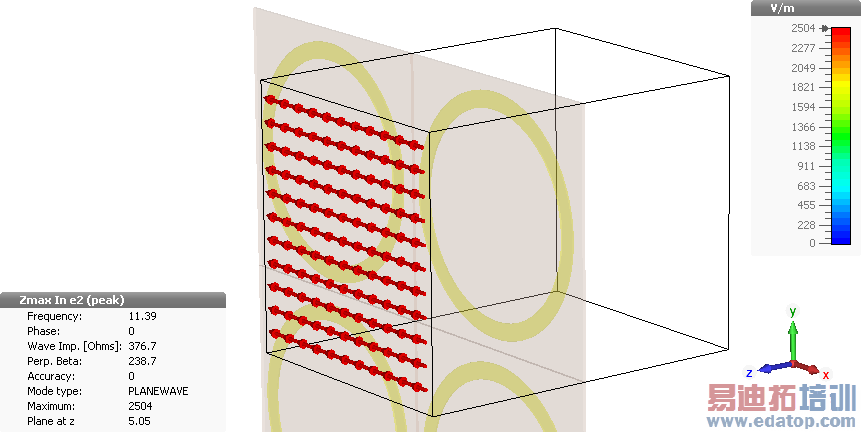
TM(0,0) mode, electric field.
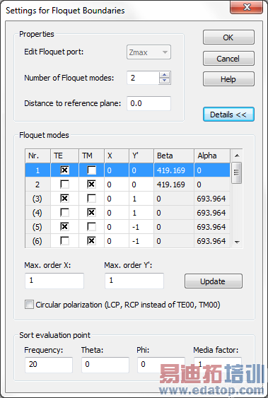
Higher order or circularly polarized Floquet modes may be defined.
o Solver Setup
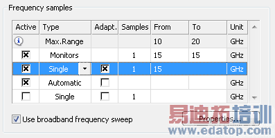
Once the geometry is constructed, the simulation conditions are set up, and some field monitors have been defined, the frequency solver can be started (with either a hexahedral or tetrahedral mesh).
The monitors' frequency is chosen as the single adaptive tetrahedral mesh refinement frequency:
Simulation results
Of primary interest in this case are the S-parameter results, which represent the reflection from and transmission through the FSS. The co-polar reflections and transmissions of both modes are almost identical due to the symmetrical circular rings (the slight difference is due to the tetrahedral mesh). The transmission is almost completely blocked at 14.81 GHz, as seen from the SZmin(1),Zmax(1) of about -53 dB, and the reflection is almost complete (SZmax(1),Zmax(1) ≈ -0.02 dB).
Please note that the adaptive tetrahedral mesh refinement usually should be performed in the pass band of a filter ratherthan in the stop band to focus on the accuracy of the transmission S-parameters. As the adaptation frequency was forced to 15 GHz, the solver detects this situation and recommends to move the adaptation frequency. Alternatively, more thanone mesh adaptation frequency can be specified. See the frequency domain solver overview for details.
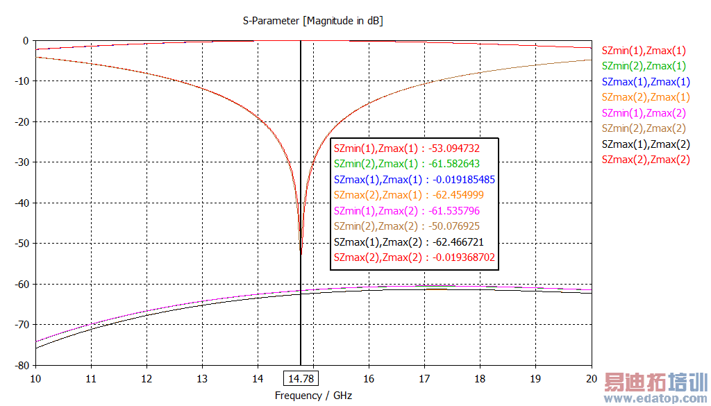
Reflection from and transmission through the FSS.
A view of the electric field magnitudes at 14.78 GHz (which can be calculated after the simulation by using the ”Calculate fields at axis marker” option from the 1D plot's context menu) reveals the two full-wavelength resonances due to the two Floquet port modes.
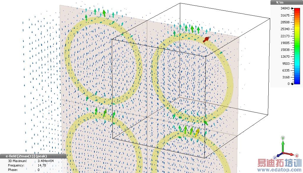
Electric fields at the resonance with the plane wave Floquet mode TE(0,0) excited.
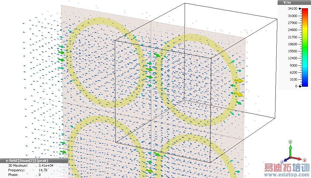
Electric fields at the resonance with the plane wave Floquet mode TM(0,0) excited.
Parameter sweep analysis
As mentioned previously, the dependence of the FSS resonant frequency on the angle of the incident plane wave is of interest. A parameter sweep can be set up to vary the incident angle, in this case theta from 0 to 50 degrees. The reflection and transmission coefficients can be investigated as a post-processing step, either by viewing the parametric results for the S-parameters, or by extracting data with a result template. In the following here the transmission coefficients of TE and TM mode will be compared.
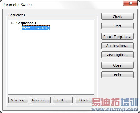
A parameter sweep can be set up to observe the effect of scan angle on the FSS transmission characteristics.
The transmission coefficient of the TE mode shows greater dependence on variation of the scan angle in theta than the TM mode does. This is to be expected since the incident wave’s direction of incidence has not changed relative to the top and bottom of the rings (as oriented in the field plots above), only to the left and right.
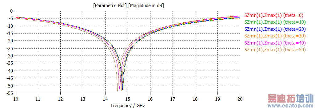
Effect of varying theta on transmission of the TE mode through the FSS.
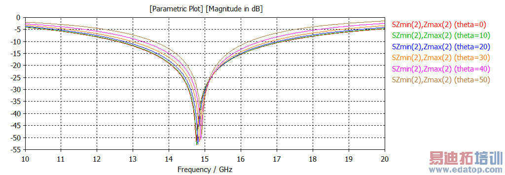
Effect of varying theta on transmission of the TM mode through the FSS.
Conclusion
This tutorial has described how CST MWS may be used for the simulation of frequency selective surfaces. The set up of the simulation may be greatly simplified by using a template which configures the simulation appropriately and generates Floquet port modes with parameterized incident angle of the plane wave. Once the geometry of a single cell has been constructed the periodicity can be set up very flexibly. Reflections from and transmissions through the FSS can be observed easily using the familiar S-parameter representation. Finally, a parameter sweep of the incident wave angle can be performed to investigate its effect on the performance of the FSS.
CST微波工作室培训课程套装,专家讲解,视频教学,帮助您快速学习掌握CST设计应用
上一篇: CST MWS Examples - CST2013 MWS Examples
下一篇: Lossy Loaded Waveguide - CST2013 MWS Examples
CST培训课程推荐详情>>
 最全面、最专业的CST微波工作室视频培训课程,可以帮助您从零开始,全面系统学习CST的设计应用【More..】
频道总排行
- Rectangular Waveguide Tutorial
- FSS: Simulation of Resonator
- CST2013 MWS Examples: Thermal C
- Dipole Antenna Array - CST201
- CST MWS Examples - CST2013 M
- Microstrip Radial Stub - CST2
- Dielectric Resonator Antenna -
- Interdigital Capacitor - CST20
- CST2013 MWS Examples: Biological
- Lossy Loaded Waveguide - CST2