- 易迪拓培训,专注于微波、射频、天线设计工程师的培养
How to use LTD substrate file in ADS ?
录入:edatop.com 点击:
I want to simulate Transmission line in ADS momentum for that I'm trying to use substrate ,which I got from technology library(65nm TSMC) as a LTD file which I'm able to import in ADS momentum "substrate editor" but I'm not getting how to use it in layout for simulation.Could you please suggest how to do this ?
Thanks in advance.
It is not clear what your problem is - do you need help to to get started with Momentum, or is there a more specific question?
The basic workflow is this:
- You have a layout with polygons on layers
- The Momentum substrate (stackup) assigns materials and positions to the layers
- You create an emSetup for that layout cell, which tells Momentum what substrate and settings to use
Do you already have a workspace/library with the layer definitions that match your Momentum stackup (*.ltd file), or do you need help to create that now?
Thank you very much it was helpful.I have one more question,I have created layout using ADS,is there any wayI can use / import it in Cadence ?.If you could suggest any online resource that will be a great help.
Sure! You might be able to reference your ADS library (open access format) in Cadence. Or you can go the "legacy" way: export the layout in GDSII format from the ADS layout window, and import into Cadence layout.
It's working, thanks Champ.
I did transmission line (Layout) S-parameter simulation in ADS,how can I use this model in cadence schematic for simulation ? I mean is there a way we can exportthis transmission line model from ADS and use it in cadence schematic(In cadence we have ideal transmission line symbol ,I wanttouse the s-parametermodelwhich is created in ADS).
I'm not a Cadence user, but I know they have data blocks for S-parameters.
In ADS you need to create a file in Touchstone file format (SnP). There are multiple ways how to do that, one option is to invoke the data file tool from the Data Display menu: Tools > Data File Tool
Thanks
I'm trying forS parametersimulation ofdifferential transmission line in ADS ,but while doing so I'm facing issue in defining reference port (port 1 should have ref of port 2 instead of ground).I'm attaching a image of same.Could you please help me with how to do port referencing.Also I will appreciate any help regrading differential transmission line (To improve S11 and S21).Thanks in advance
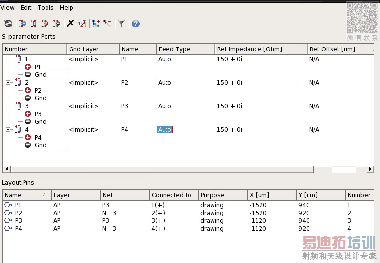
You can assign a pin as the port reference using drag & drop in this window! For example, select P2 and drag it to the terminal of P1. This creates a port with P1 and P2
I have created layout fordifferential Transmission line in ADS 2017,I did even mode termination(Fig.a) and simulation works fine but I'm not able to set odd/differentialmodetermination(Fig.b)(In figure I have shown only 2 ports but there are 4 ports).I know we can set P1and P2but I guess this will not be good way for SP simulation.Could you please helpme to set proper termination?
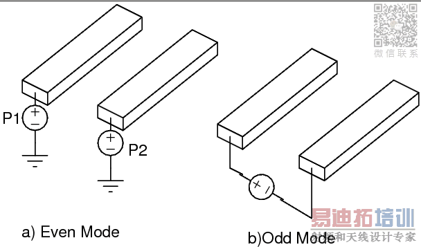
Maybe it is better to model this as a 4-port model, with 4 ports all referenced to global ground. I updated my transmission line appnote to cover that topic, and what the implications are.
https://muehlhaus.com/support/ads-application-notes/em_line_ground:Dr. Mühlhaus Consulting & Software GmbH » The ground pin confusion in EM transmission line models
I had a stackup file, in .ltd format, prepared by the foundry (HHGRACE) and I imported it into ADS to use in EM simulations. But EM editor doesn't recognize couple of layers, like Via layer. It says,
"- Invalid Substrate: Could not find layer 115 in technology for library X",
where layer 115 is one of my Conductor Via layers. What can I do for this problem? Any help would be appreciated.
Thanks..
You can add missing layers using the ADS layers dialog.
Options > Technologies > Layer Definitions
To do so, you need to have write permission to the library.
If you think all layer *should* be there: One possible issue might be that your workspace library does not have a technology yet, because your ADS settings are configured for "late" technology setup. In this case, the technology in your workspace library will be configured from the PDK when you try to add a layout.
I did what you have suggested, namely defining missing layers manually and it worked. I managed to do EM simulation although I don't know if the results are correct or not
申明:网友回复良莠不齐,仅供参考。如需专业帮助,请学习易迪拓培训专家讲授的ADS视频培训课程。
上一篇:Need help with Data Access Component ( DAC)
下一篇:Unable to install NXP model to ADS Library
ADS培训课程推荐详情>>
 国内最全面、最专业的Agilent ADS培训课程,可以帮助您从零开始,全面系统学习ADS设计应用【More..】
- Agilent ADS教学培训课程套装
- 两周学会ADS2011、ADS2013视频教程
- ADS2012、ADS2013射频电路设计详解
- ADS高低阻抗线微带滤波器设计培训教程
- ADS混频器仿真分析实例视频培训课程
- ADS Momentum电磁仿真设计视频课程
- ADS射频电路与通信系统设计高级培训
- ADS Layout和电磁仿真设计培训视频
- ADS Workspace and Simulators Training Course
- ADS Circuit Simulation Training Course
- ADS Layout and EM Simulation Training Course
- Agilent ADS 内部原版培训教材合集