The most popular topology for PFC (power-factor-corrected) preregulators is the boost converter, which has continuous input current that you can manipulate with average-current-mode-control techniques to force input current to track changes in line voltage.
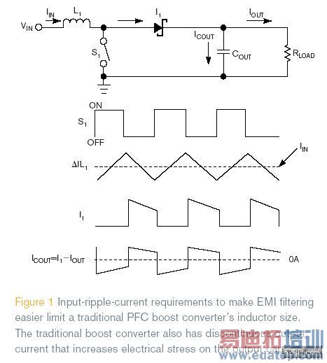
shows a traditional single-stage boost. (To more easily explain the circuit operation, this article refers to dc inputs.) The change in inductor ripple current, 腎L
1, is directly at the converter’s input and may require filtering to meet EMI specifications. The diode output current, I
1, is discontinuous and requires the output capacitor, C
OUT, to filter it. In this topology, the output-capacitor ripple current, I
COUT, is high and is the difference between I
1 and the dc output current, I
OUT.
Interleaving boost converters
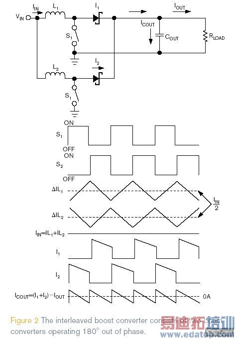
shows the functional diagram of a two-phase interleaved boost converter, which comprises two boost converters operating 180?out of phase. The input current is the sum of the two inductor currents, IL
1 and IL
2. Because the inductor’s ripple currents are out of phase, they cancel each other out and reduce the input-ripple current that the boost inductors cause. The best input-inductor-ripple-current cancellation occurs at 50% duty cycle. The output-capacitor current is the sum of the two diode currents, I
1+I
2, minus the dc-output current, which reduces the output-capacitor ripple, I
OUT, as a function of duty cycle. As the duty cycle approaches 0, 50, and 100%, the sum of the two diode currents approaches dc. At this point, the output capacitor has to filter only the inductor-ripple current.
Input-ripple-current reduction
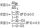
The following equations and
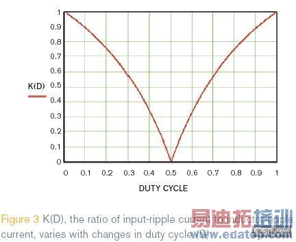
show how the ratio of input-ripple current to inductor-ripple current, K(D), varies with changes in duty cycle. It is important to remember this variance when selecting inductors for the interleaved boost converter.

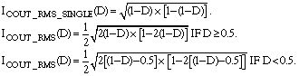
shows the normalized output capacitor rms current in a single-stage boost converter, I
COUT_rms_single(D), and the normalized rms current in a two-stage interleaved boost converter, I
COUT_rms(D), as a function of duty cycle. The
demonstrates that the output-capacitor-ripple current in a two-phase interleaved boost converter is roughly half that of a traditional single-stage boost converter, reducing the electrical stress on the output-filter capacitor.
Evaluating inductor size
To evaluate the benefits of interleaving PFC preregulators’ reduced boost-inductor size, I conducted a mathematical comparison between a single-stage and a two-phase boost preregulator (
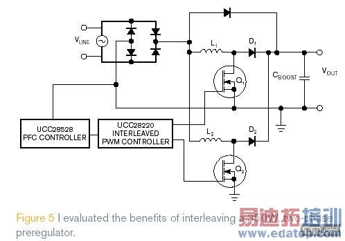
). The design requirements were a maximum output power, P
OUT, of roughly 350W; a minimum line input, V
INMIN, of 85V rms; a maximum line input of 265V rms; and an estimated converter efficiency of 95%. The inductors have a switching frequency, f
S, of 100 kHz. The inductors have an input-ripple-current requirement of 30%, and the inductors of both topologies have the highest inductor-ripple currents that occur at the minimum input and maximum input current.
I selected the inductors for both designs based on the worst-case ripple current. For a converter for a universal input, this point occurs at the minimum ac input at the peak line voltage, with the converter operating at a minimum duty cycle of 0.67.
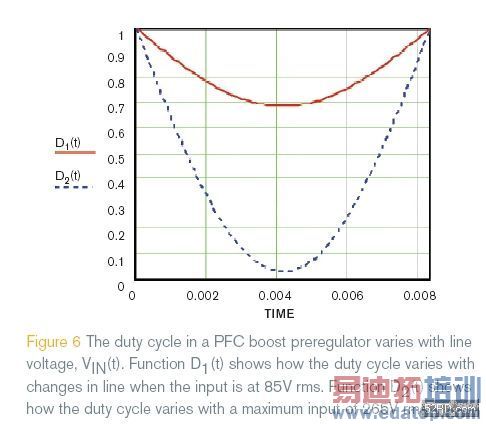
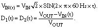
shows how the duty cycle varies with line voltage V
IN(t). Function D
1(t) shows how the duty cycle varies with changes in line when the input is at 85V rms. Function D
2(t) shows how the duty cycle varies with a maximum input of 265V rms. When the converter is operating at a maximum input of 265V rms, the maximum inductor-ripple current occurs when the input voltage is at half the output voltage. As the line voltage approaches the output voltage, the duty cycle decreases, reducing the inductor-ripple current.
The inductor-ripple current in a single-stage PFC preregulator is evident at the converter’s input. A single-stage PFC inductor for a universal input would be roughly 450 礖. I based this calculation on where the inductor-ripple current was greatest at 85V rms input and 0.67 minimum duty cycle.

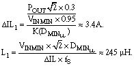
The dual-interleaved inductor has the same input-current-ripple requirements as the traditional preregulator. The change in inductor current in one of the interleaved boost stages is roughly 3.4A. Variable minimum duty cycle at the minimum rms input voltage requires an inductance of roughly 245 礖梐bout half the inductance a single-stage PFC preregulator at the same power level requires.
Lab results
I evaluated a dual-interleaved boost converter using 200-礖 inductors for L1 and L2 and the input current. The worst-case inductor-ripple current occurs when the converter operates at low input at the peak of the line. The oscilloscope plot in
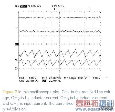
shows the inductor currents of L
1 and L
2 with an input of 85V rms. CH
1 is the rectified line voltage, CH
2 is L
1 inductor current, CH
3 is L
2 inductor current, and CH
4 is input current. The current-conversion ratio is roughly 4A/division.
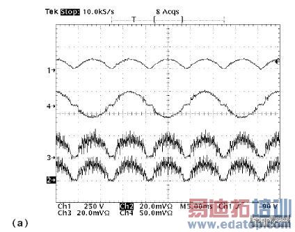 and
and 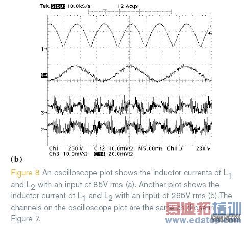 show the input-line and inductor-ripple currents at maximum load. The channels of the scope plots are the same as in
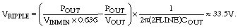
. These waveforms clearly demonstrate a clean input-current waveform for Channel 4. This two-phase, interleaved-PFC design uses a 220-礔 output capacitor. At full load for a single-stage, 350W PFC preregulator, the output-capacitor ripple would be roughly 33.5V. For a two-phase, interleaved PFC, the output ripple should be less than half of the single stage. The prototype’s output-ripple voltage at full load is roughly 13V (

).
Determining whether the prototype could meet current harmonic specifications EN61000-3-2 requires the prototype’s input harmonics’ full-load power. The first harmonic is the rms input current at 60 Hz. The proceeding harmonics are well within CH61000-3-2 Class D specifications (

).
Interleaving PFC preregulators allows power-supply designers to reduce inductor magnetic volume. The inductor-ripple-current cancellation at the input of the power converter allows designers to reduce the inductance by roughly half. Interleaving also reduces the ripple current in the boost capacitor, alleviating electrical overstress on the output capacitor. With no filtering on the prototype circuit, the design achieves EN61000-3-2 Class D current-harmonic specifications. It has a slightly more complicated control scheme with a higher component count, but, in high-power applications, this trade-off is well worth it.