- 易迪拓培训,专注于微波、射频、天线设计工程师的培养
CST2013: Mesh View (Hexahedral)
录入:edatop.com 点击:
 Home: Mesh
  Mesh View
In the mesh view, the most recently generated mesh is visualized and all actions concerning the further mesh creation may be performed. The automatic mesh generator may be controlled and the resulting mesh will be displayed. This view should always be checked before a simulation is started because the mesh has a strong influence on the achievable accuracy of the results.
Here, we concentrate on the range of functions available for hexahedral meshes. More information about the demands on hexahedral meshes may be found in the Mesh Generation Overview (Hexahedral). For tetrahedral meshes, see Mesh View (Tetrahedral) and Mesh Generation Overview (Tetrahedral). For surface meshes, see Mesh View (Surface) and Mesh Generation Overview (Surface).
Entering the mesh view
The mesh view may be entered by pressing the Mesh: Mesh Mesh View button .
The main plot window in the mesh view
The main plot window shows the mesh in one plane. All mesh control points (fixpoints and density points) used or created by the automatic mesh generator are shown (red, blue and yellow dots) if they are activated. Furthermore, if the corner correction option is active, all edges where this scheme may be applied are marked (green lines).
The mesh plane also operates like a cutting plane. This is to avoid the structure hiding the plane. All visualization options of the normal cutting plane may be used. Additionally, two buttons ( Mesh: Mesh Plane Mesh Increment Index( ) and Mesh: Mesh Plane Mesh Decrement Index(
 )) are available that move the mesh plane up and down for one mesh index. The orientation of the mesh plane may be changed by choosing Mesh: Mesh Plane X/Y/Z Normal (

 ).
).
Some useful information is plotted into the window as well. On the bottom of the window, the index and the location of the current mesh plane is plotted.
View Option: The visualization of the mesh control points and the edges treated by the corner correction may be controlled by choosing categories in Mesh: Mesh ControlShow ( )or the corresponding setting in View View Options... (see View Options).
Navigation tree
The Navigation Tree contains the Mesh Control Folder. If you click on that folder you are automatically in the mesh view mode.
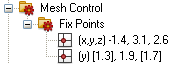
| In this folder, all user-defined fixpoints (see below) are listed. The location is printed and the direction(s) in which they will affect the mesh. The active directions are those in ”round” brackets. The values in ”square” brackets are irrelevant for the mesh generation. |
Expanded critical cells/areas
After the structure has been meshed, some mesh cells/areas might have been filled with PEC. In this case, a warning message on top of the Main plot window will appear (for more information see Mesh Generation Overview ).
Fixpoints and density points
Fixpoints: The automatic mesh generator will detect the important points inside the structure and locate fixpoints at these positions. If possible, a mesh node will be located there. When the mesh view is activated, fixpoints are depicted by red dots.
Density control points: These control points are used by the automatic mesh generator to refine the mesh in a particular region if necessary. This is the case, for instance, when the Refine at PEC Edges option is active. When the mesh view is activated, the density control points will be depicted as yellow dots.
User defined fixpoints: The mesh creation may be performed with even more flexibility by creating user defined fixpoints (blue dots). These user defined fixpoints may be created at characteristic points of the model. They are associated to the structure and enable advanced mesh control with fully parametric modeling. To set a user defined fixpoint, select the desired shape and use one of the following tools:
| Modeling: Picks |
| Modeling: Picks |
| Modeling: Picks |
| Modeling: Picks |
| Modeling: Picks |


You may specify the direction(s) in which these fixpoints will be effective. This may be carried out either through the context menu of the fixpoints or by selecting Mesh: Mesh ControlFixpoint ListUse <x,y,z> Coordinate (

 ).
).
Controlling the mesh by changing its parameters
The behavior of the automatic mesh generation may be changed by adjusting its parameters. These parameters may be accessed from the mesh properties dialog box (Mesh: Mesh ControlGlobal Properties,  ) and the corresponding specials sub dialog box in the Mesh Dialog.
Controlling the mesh for specific structure elements
It is possible to set several structure element specific mesh control values. They may be reached by selecting the corresponding object and choosing Local Mesh Properties from the context menu.
If specific mesh properties are set for a shape this is visualized in the mesh view with the  icon.
icon.
Consider for Automesh: Some structure elements may produce many mesh control points and, with this, a very dense mesh, although this structure element may not be important for the simulation. In these cases, the generation of control points for this element may be switched off.
Priorities: The priority number defines an ”importance” of the different solids for the mesh generation. If one solid has a higher priority than the other one, its mesh requirements will be fulfilled in advance of the less important one.
Maximum Mesh Step Width: For structure elements of high importance for the simulation, a maximum step width for every coordinate direction may be specified.
Manual mesh generation
Besides the automatic mesh generation, a manual mesh mode is also available. The automatic mesh generation is switched off as soon as a manual mesh operation is performed.
You may manually add fixpoints by simply clicking at an edge endpoint (Modeling: PicksPicks  ) or a circular edge (Modeling: PicksPick PointPick Circle Center
  ), depending on the activated mode. After clicking a proper item, a new fixpoint will be set to the specified location or an existing fixpoint at this location will be selected.
After selecting a fixpoint, it may be deleted by choosing Delete Fixpoint(s) from the context menu or by pressing the DELETE key.
You may also add, delete and move fixpoints from within the fixpoint list dialog box (Mesh: Mesh ControlFixpoint List,  ).
).
After two fixpoints have been selected (selecting the first one and the holding the CTRL key pressed while selecting the second one) you may also add intermediate fixpoints by choosing the Intermediate option in the fixpoint list dialog box.
CST微波工作室培训课程套装,专家讲解,视频教学,帮助您快速学习掌握CST设计应用
上一篇:CST2013: Fixpoint (Line Endpoint) Creation Mode
下一篇:CST2013: Pick Edge Center Mode
CST培训课程推荐详情>>
 最全面、最专业的CST微波工作室视频培训课程,可以帮助您从零开始,全面系统学习CST的设计应用【More..】
频道总排行
- CST2013: Mesh Problem Handling
- CST2013: Field Source Overview
- CST2013: Discrete Port Overview
- CST2013: Sources and Boundary C
- CST2013: Multipin Port Overview
- CST2013: Farfield Overview
- CST2013: Waveguide Port
- CST2013: Frequency Domain Solver
- CST2013: Import ODB++ Files
- CST2013: Settings for Floquet B