- 易迪拓培训,专注于微波、射频、天线设计工程师的培养
CST2013: Sources and Boundary Condition Problem Handling
录入:edatop.com 点击:
This page contains a list of the most important warning and error messages in the context of source, boundary and material modeling together with a detailed explanation of the meaning and proposal for handling and resolution.
Contents
Excitation sources
Waveguide ports
Port number "xxx" is completely filled with metal. Maybe the background material is defined as PEC?
All degrees of freedom inside the port plane lie inside metal material, so that no mode pattern can be calculated. Please check whether the background material is defined as PEC or the port is located inside a metal object.
Some higher order propagating modes at port "xxx" are not considered in time domain calculation. This possibly leads to an inaccurate energy balance. Consider to increase the number of modes or decrease the upper frequency limit.
In case of a multi-conductor port usually TEM or QTEM modes are of interest. Depending on the dimension of the waveguide port and the upper limit of the global frequency range, there might also occur higher order propagating modes in addition. Usually this is not intended and these modes can be stopped from propagating by lowering the upper frequency limit. In principle it is also possible to reduce the port size, but this has to be done very carefully in order to still sufficiently cover the mode patterns of the relevant TEM and QTEM modes. In case that the higher order propagating modes are intended as e.g. box modes, the number of modes should be increased to consider these modes correctly for simulation.
Some higher order evanescent modes at port "xxx" are not sufficiently decaying concerning the structure dimension. This possibly leads to an inaccurate energy balance. Consider to increase the number of modes or decrease the upper frequency limit.
In case of a multi-conductor port usually TEM or QTEM modes are of interest. Depending on the dimension of the waveguide port and the upper limit of the global frequency range, there might also occur higher order evanescent modes. Usually these modes have no important influence on the simulation, because they are decaying over a very small distance. However, in case that their damping constant is small their influence cannot be neglected anymore. By lowering the upper frequency limit these modes will be damped more intensively. In principle it is also possible to reduce the port size, but this has to be done very carefully in order to still sufficiently cover the mode patterns of the relevant TEM and QTEM modes. In case that the higher order evanescent modes are intended as e.g. box modes, the number of modes should be increased to consider these modes correctly for simulation.
At least one propagating mode at port "xxx" is not considered in the time domain calculation! (At least one mode shares the same beta with considered mode(s) -> degeneration) It might be better to increase the number of modes at port "xxx".
"nnn" degenerated mode(s) at port "xxx" is/are not considered in time domain calculation! It might be better to increase the number of modes at port "xxx".
This warning is shown when some propagating TE or TM modes are not considered in the simulation. Usually this is not intended and the modes could be taken into account by increasing the number of modes. In case of missing degenerated modes (sharing the same propagation constant) this is even more important to provide an accurate simulation result.
The first mode at inhomogeneous port "xxx" is hybrid. This could lead to an inaccurate energy balance. Please check your structure.
Hybrid modes exist at inhomogeneous port "xxx". This could lead to an inaccurate energy balance. Please check your structure.
When the calculated field pattern at the port is a six-component mode, which can not be decomposed into two or more degenerated modes, this warning will be generated. Typically this is caused by incorrect structure modeling such as a microstrip transmission line where the ground plane does not intersect the port. Please check your port setup.
There exist non-(Q)TEM modes for the inhomogeneous port "xxx". This may lead to an inaccurate energy balance. Consider to decrease the upper frequency limit.
Although expected for a multiconductor port, one or more modes could not be classified as (Q)TEM at some frequency point. This usually happens at higher frequencies when longitudinal field components become stronger. The modes are classified as TE/TM or hybrid in this case. Consider to decrease the upper frequency limit.
The inhomogeneous port "xxx" shows a strong dispersive behavior. Please increase the number of modes.
At inhomogeneous ports it is necessary to track the mode pattern over frequency in order to provide correct scattering parameters. However, this is only possible if the mode patterns vary not too much between the lower and upper frequency limit. Furthermore, mode propagation constants might interchange over frequency such that the corresponding mode cannot be found anymore. In this case it might be necessary to increase the number of modes.
Inhomogeneous port accuracy enhancement: Port "xxx" shows a strong dispersive behavior which could lead to inaccurate S-parameter results. Please decrease the upper frequency limit.
The inhomogeneous port accuracy enhancement can compensate errors introduced by frequency dependent mode patterns. However, this is only possible if the mode patterns vary not too much between the lower and upper frequency limit. If this warning is issued please consider decreasing the upper frequency limit or splitting the frequency range in higher and lower bands.
Multipin ports
Multipin port "xxx" is strongly inhomogeneous, i.e. the corresponding modes represent combinations of field patterns with different propagation properties. This may lead to an inaccurate energy balance.
At inhomogeneous multipin ports QTEM modes are combined to satisfy the specified potential set definition. If the propagation constants of the modes differ too much they cannot be considered as degenerate anymore and they should not be combined.
Some (Q)TEM modes were not found on port "xxx". Consider to increase the mode calculation frequency.
To create a multpin port mode that satisfies the specified potential settings it is necessary to linearly combine the existing degenerated TEM or QTEM modes. If the mode calculation frequency is very low not all modes may be available. Consider increasing the mode calculation frequency in the specials dialog of the time domain solver or adjusting the global frequency range.
Some (Q)TEM modes are not considered at port "xxx". This may lead to an inaccurate energy balance.
It is important that the number of defined potential sets equals the number of degenerated QTEM or TEM modes in the waveguide. If not a large part of the field may propagate in the unconsidered mode patterns. The waveguide port boundary still treats these fields internally but they will not contribute to the scattering matrix and may therefore lead to an inaccurate energy balance.
The multipin potential settings on port "xxx" result in linearly dependent field patterns. Please note that the mode fields will be orthogonalized to ensure stability.
The defined potential sets should result in linear independent field patterns, e.g. the “even” and “odd” modes in a three conductor port. Otherwise the fields at the port cannot properly be decomposed into mode amplitudes. Please check whether the potential set definition is meaningful or consider treating the port as single-ended.
Multipin port "xxx" calculates a zero mode pattern. Maybe your structure shows some unwanted electric cavities. Changing boundaries from electric to magnetic possibly solves this problem.
This warning is shown when a multipin port area has some decoupled mode regions, so called cavities. This might happen either by an incorrect port setup or by electric transversal port boundary conditions which creates cavities between themselves and the outer port conductor. In the latter case changing the boundary conditions to magnetic can remove these unwanted cavities.
Floquet ports
At least one propagating Floquet mode is not considered at port "xxx". Please increase the number of modes at this port.
It is important to consider all propagating modes in the simulation, since those parts of the fields attributed to unconsidered modes will be reflected at the Floquet port boundary. This usually may lead to inaccurate S-parameters. Please include all propagting modes by increasing the number of modes considered at the Floquet port in the Settings for Floquet Boundary dialog.
Materials
The material "xxx" has a very high conductivity for the given mesh. It may be better to use a lossy metal type for this material.
The material "xxx" has a very low conductivity for the lossy metal model. It may be better to use a normal type for this material.
In order to simulate conductive material, the mesh has to be refined such, that the field variation (e.g. skin depth) is sufficiently discretized. This might lead to an extremely fine mesh representation for highly conductive materials. For these kind of materials the "lossy metal" model should be applied, which takes into account the skin effect without refining the mesh. However, if the skin depth is larger than the metal thickness and a radiation effect through the metal is of importance, the “lossy metal” model cannot be used anymore and type "normal" should be selected. This is also true for materials with very low conductivity where the "normal" material type offers a more accurate simulation result than the "lossy metal" surface model.
The two warning messages indicate which material type selection should be preferred. Please find a more detailed description on these and other material types on the Material Overview page.
Boundaries
Lumped Network Elements
At least one end point of "xxx" is not connected to any good conductor.
At least one end point of the following discrete ports or lumped elements is not connected to any good conductor: ...
Some discrete ports or lumped network elements were found which are not connected to any good conductor, for instance "floating" some distance away from a conductor due to modelling tolerances. Especially at low frequencies, results then can differ from what is expected, since the connection to the remaining three-dimensional representation of the circuit is uncertain. Please zoom in to inspect the connectivity of the network elements, and create them again if necessary (preferably pick a part of the conductors the network element should be connected to).
The check for floating elements considers the end points of edge lumped network elements. This also the case for the face ports and face lumped network elements: they have an alternative edge lumped network element associated with them which is used by solvers that do not support the face type lumped network elements. For the sake of simplicity and performance of the connectivity check, these associated edges will be used for the face lumped network elements. For each of their end points, the check tries to find a conductor body that contains the point. PEC and lossy metal solids are considered as good conductors, as well as normal materials with a conductivity higher than 1000 S/m.
Face lumped elements are only supported over rectangular, cylinder-barrel or radial surfaces.
The error message is displayed if the shape of the face lumped network elements is not supported or not recognized, for instance due to modelling accuracy. Rectangular, cylinder-barrel and radial lumped network elements are supported. They are illustrated by the first three lumped network elements in the picture below. Please delete and re-create the lumped network elements so that their shape is either rectangular, cylinder-barrel, radial like, or use straight edge lumped network elements.
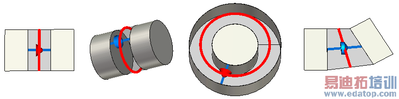
from left to right: a rectangular discrete port, a cylinder-barrel lumped network element, a radial discrete port, a lumped network element of different shape
The dimensions of the discrete face port "xxx" are not consistent:
The length is "yyy" in the model and "zzz" in the mesh.
The width is "yyy" in the model and "zzz" in the mesh.
The inner radius is "yyy" in the model and "zzz" in the mesh.
The general purpose frequency domain solver with tetrahedral meshverifies the dimensions of the discrete face ports to check if the mesh representation ofthe discrete face port agrees with how the source was modeled.In order to apply one of the face port definitions shown in the picture above, the characteristic dimensions must be known to the solver and the meshneeds to be consistent with that data.
One reason for this error message is an overlap of the discrete face port with solids made of PEC or lossy metal material. They effectively reduce the area of the discrete face port.
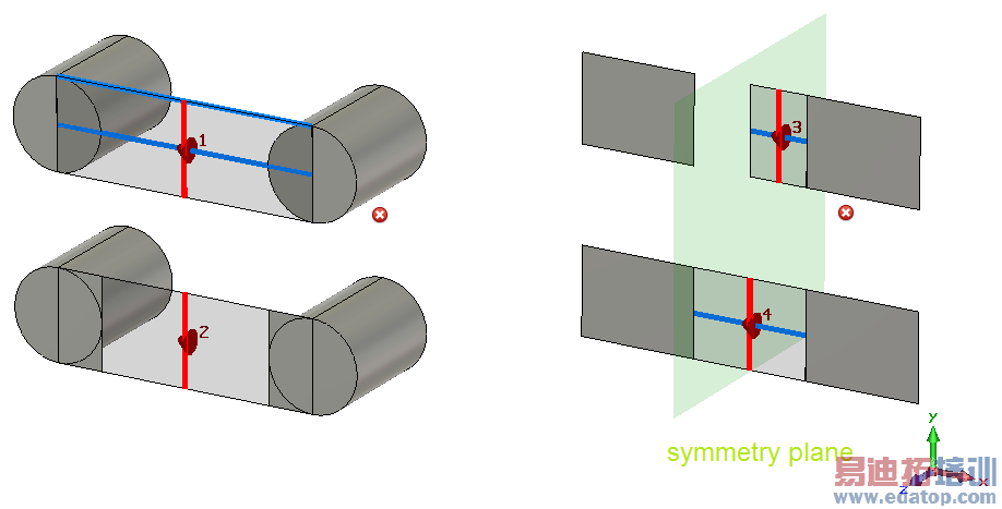
Another case where this error message is shown may occur if symmetry conditions are presentand the face port touches the symmetry plane without being symmetric to the symmetry condition.Please enlarge the discrete face port in that case.
The two examples below show the unsupported case at the top and the recommended solution at thebottom:
CST微波工作室培训课程套装,专家讲解,视频教学,帮助您快速学习掌握CST设计应用
上一篇:CST2013: Arc Creation Mode
下一篇:CST2013: VBA Macro Layout
CST培训课程推荐详情>>
 最全面、最专业的CST微波工作室视频培训课程,可以帮助您从零开始,全面系统学习CST的设计应用【More..】
频道总排行
- CST2013: Mesh Problem Handling
- CST2013: Field Source Overview
- CST2013: Discrete Port Overview
- CST2013: Sources and Boundary C
- CST2013: Multipin Port Overview
- CST2013: Farfield Overview
- CST2013: Waveguide Port
- CST2013: Frequency Domain Solver
- CST2013: Import ODB++ Files
- CST2013: Settings for Floquet B