- 易迪拓培训,专注于微波、射频、天线设计工程师的培养
CST2013: Special Mesh Properties - Surface Mesh
录入:edatop.com 点击:
Home: Mesh Global Properties SpecialsSurface mesh
This dialog allows you to control the overall surface meshing process. In most cases you will not need to change the default settings. Please note that changes are applied to both mesh types, surface and tetrahedral.
You can choose between two surface mesh generation methods in the Mesh Method tab. Available methods are
General purpose meshing and
Fast surface meshing,
see below. Depending on the selected method, you can tune the following settings:Depending on the
General purpose meshing active:
Surface optimization
If this field is checked (recommended), the mesh connectivity of the preliminary surface mesh is changed to improve the mesh quality and to yield a good matching between discrete and continuous surface areas.
Surface smoothing
The slider controls the amount of vertex repositioning that is performed to enhance the mesh quality. A high value means that vertices are allowed to move larger distances; note that this may smear out transitions in mesh size. A medium position is recommended.
Curvature refinement
Curvature refinement allows the mesh to be automatically refined to match the curvature of the entities in the geometric model.
Curvature refinement ratio: The mesh size is selected such that d/h is less than the given ratio everywhere, see the figure on the right for the definition of d and h. Hence, the smaller the value the finer the mesh.
Maximum number of steps from curvature ref.: This value defines the smallest mesh size resulting from the curvature refinement. This mesh size is defined as a fraction of the largest edge of the model bounding box, e.g. value 100 means that the smallest mesh size resulting from curvature refinement equals to 1/100 of the bounding box edge.
Anisotropic curvature refinement: If this option is checked, the curvature based refinement is anisotropic, e.g. a cylindrical surface will refine along circumference only. This may be useful if a small number of elements is intended. Note that anisotropic refinement may increase the meshing time. | 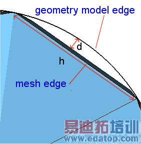 |
Density transitions
The slider controls how a finer mesh size propagates to adjacent areas where the mesh size is coarser. This is particularly relevant if strongly different mesh sizes are locally defined for adjacent shapes.
Smooth means that the mesh size will approximately double with each element until it reaches the coarser mesh size. As the slider will be moved to the left, the transition in size will occur in fewer elements (larger jumps in element size). At the slider position rapid the mesh will jump to the coarser mesh size as fast as possible with no transition. In most cases, a medium position is recommended.
Small feature suppression
Detects small features in the model based on the tolerance specified and performs suppression. This method can be used to remove unintended features like sliver faces from the model. The concept is to consider a ball of diameter equal to the specified value and to move it along the periphery of a model face. If the face is completely covered by the generated area, it is considered small and will be suppressed. Model edges shorter than the tolerance will be suppressed as well. For zero tolerance all details are considered. The feature suppression might lead to an invalid model. In this case, the specified tolerance will be decreased automatically in order to obtain a valid model. If this is not successful, an error message will be printed.
Examples: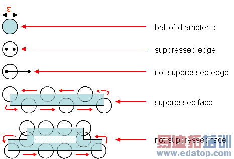
Fast surface meshing active:
Curvature refinement
In this box you can specify a surface and a normal tolerance.
The surface tolerance is the distance between the mesh face and the part of the surface it is representing. By setting this value, the user specifies how accurately the mesh faces represent the surface. It is desirable to provide surface tolerance when mesh faces obtained with normal tolerance do not represent the surface well.
Here you have to specify whether the surface tolerance is given as a relative or absolute value. Relative means that a surface tolerance is used which is independent of the model size; i.e. the given number is multiplied by a fraction (for example, 1/500th) of the diagonal of the bounding box of the body. For example, when the surface tolerance is set to 10 combined with "Relative", then 1/50th of the length of the diagonal is used as the actual surface tolerance. Increasing the surface tolerance results in coarser and fewer mesh faces, whereas decreasing the surface tolerance results in finer and more mesh faces. If the scale of the model grows (or shrinks), the pattern and the number of mesh faces remain the same, but the size of the mesh faces grows (or shrinks). Absolute means that the value is used as specified. When the value of surface tolerance is 0, this value is ignored for surface meshing.
The normal tolerance specifies the maximum angle between the surface normals at two adjacent triangles on a smooth surface. By setting this normal deviation refinement, the user specifies how accurately the facets are representing the surface and the quality of rendering desired. It is desirable to use this refinement control because it is independent of the model size.
If the Anisotropic curvature refinement option is checked, the curvature based refinement is anisotropic, e.g. a cylindrical surface will refine along circumference only. This may be useful if a small number of elements is intended. Note that anisotropic refinement may increase the meshing time.
Remeshing of initial triangulation
The fast surface meshing method works in two steps. First an initial triangulation is generated which resolves the geometry adequately and takes the user-defined mesh sizes into account. Then the initial triangulation is remeshed in order to improve the mesh quality for computational purposes.
Four different options are available. If the user-defined mesh size is much larger than the geometry dimensions (edge lengths, curvatures) the resulting mesh will depend strongly on the selected remeshing option. If the user defined mesh size is much smaller than the geometry dimensions the resulting meshes will be similar.
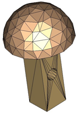
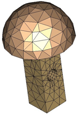
Decimation and enrichment: This is the default setting. The quality of the initial triangulation is improved by optimization and by removing or adding points and edges. This mesh option is more time consuming than the others options, but controls the mesh quality automatically.
Decimation: The quality of the initial triangulation is improved by optimization and decimation. This option is faster than Decimation and enrichment. However, the quality is not completely controlled automatically. By decimation of the initial triangulation it is possible to remove for instance singular mesh points in the initial triangulation, e.g. the poles of spheres which are surrounded by many triangles with low aspect ratio. On the other hand it is not possible to improve the quality in general since no additional mesh points will be inserted.
Simple improvement: The initial triangulation is only modified by topological optimization like edge swapping in order to improve the quality. This meshing method is even faster than Decimation and Enrichment. However, since no mesh points are removed or added the element quality of the initial triangulation can only be slightly improved.
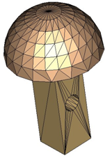
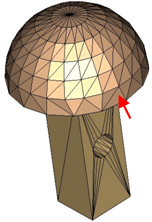
None: The initial triangulation is left unmodified and will be used as surface mesh. This is the fastest meshing method, but there is no automatic control of the mesh quality. This option might be useful if the model geometry is already defined by a triangulation for computational purposes, for instance if the NASTRAN import has been used. In this case a surface mesh is generated that is usually very similar or identical to the original mesh. Another typical application is to generate meshes with very good and regular geometry description while controlling the quality of the triangles by setting appropriate local mesh densities.
|
|
|
|
None (initial triangulation) | Simple improvement (like edge swapping) | Decimation (reduce singular mesh points) | Decimation and enrichment (additional points and edges) |
Gradation
The slider controls how a finer mesh size propagates to adjacent areas where the mesh size is coarser. This is particularly relevant if strongly different mesh sizes are locally defined for adjacent shapes.
Smooth means that the mesh size will approximately double with each element until it reaches the coarser mesh size. As the slider will be moved to the left, the transition in size will occur in fewer elements (larger jumps in element size). At the slider position rapid the mesh will jump to the coarser mesh size as fast as possible with no transition. In most cases, a medium position is recommended.
Layer stackup
This option allows to adjust the limit L for the shielding plane detection for PEC like sheets. The surface area of the sheet A_s will be compared with the surface area of the corresponding bounding box plane A_b. If the condition A_s/A_b*100 > L is fulfilled the sheet will be considered as infinite shielding plane and no mesh will be created for this PEC sheet. Holes and gaps will be considered as apertures and will be meshed.
The local mesh property "Layer stackup type" has to be set to the default value "Automatic".
OK
Accepts the changes and closes the dialog.
Close
Closes this dialog box without performing any further action.
Apply
Accepts the changes without closing the dialog.
Help
Shows this help text.
See also
Special Mesh Properties, Mesh Properties (Tetrahedral), Local Mesh Property (Tetrahedral), Mesh Generation Overview (Tetrahedral), Mesh View (Tetrahedral), Mesh Properties (Surface), Local Mesh Property (Surface), Mesh Generation Overview (Surface), Mesh View (Surface)
CST微波工作室培训课程套装,专家讲解,视频教学,帮助您快速学习掌握CST设计应用
上一篇:CST2013: Special Mesh Properties - General
下一篇:CST2013: Special Mesh Properties - Refinement
CST培训课程推荐详情>>
 最全面、最专业的CST微波工作室视频培训课程,可以帮助您从零开始,全面系统学习CST的设计应用【More..】
频道总排行
- CST2013: Mesh Problem Handling
- CST2013: Field Source Overview
- CST2013: Discrete Port Overview
- CST2013: Sources and Boundary C
- CST2013: Multipin Port Overview
- CST2013: Farfield Overview
- CST2013: Waveguide Port
- CST2013: Frequency Domain Solver
- CST2013: Import ODB++ Files
- CST2013: Settings for Floquet B