- 易迪拓培训,专注于微波、射频、天线设计工程师的培养
CST2013: Changing the Structure's View
录入:edatop.com 点击:
You may change the view to your structure at any time (even during shape generation) by some simple commands that will be explained in the following section.
The view will change whenever you drag the mouse while holding the left button pressed, depending on the mode selected. The mode may be selected either from the Ribbon by choosing View: Mouse Control Zoom/Pan/Rotate/Dynamic Zoom/Rotate in Plane and View: Change ViewReset View/Reset View to Selection:
|
|
|
|
|
|
|
Zoom |
Pan |
Rotate
|
Dynamic Zoom |
Rotate in Plane |
Reset View |
Reset View to Selection |


Mode
The mode setting effects the behavior as follows:
Zoom: In this mode, a rubber-band rectangle will be defined by dragging the mouse. After releasing the left mouse button, the zoom factor and the view location will be updated so that the rectangle fills the screen.
Pan: The structure will be translated in the screen plane following the mouse cursor movement.
Rotate: The structure will be rotated around the two screen axes.
Dynamic zoom: Moving the mouse upwards will decrease the zoom factor while moving the mouse downwards increases the zoom factor.
The dynamic zoom may also be controlled with the mouse wheel. By default the origin for this operation is located in the center of the screen. Optionally, pressing the CTRL key while using the mouse wheel performs a zoom operation around the current mouse pointer location.
Rotate in Plane: The view plane will be rotated.
The dynamic view adjusting mode is always exited when the left mouse button is released. You may reset the zoom factor by choosing View: Change ViewReset View from the main menu or from the context menus. Alternatively, you may press the corresponding item in the view Ribbon tab.
One of the most important view-changing commands is activated by View: Change ViewReset View to Selection or by pressing SPACE. This command will zoom the defined structure to a point where it fits well into the drawing window. If you have selected a part of the structure SHIFT+SPACE will zoom to the selected object only.
Because changing the view is a frequently used operation that will sometimes be necessary even during the process of the interactive shape creation, some useful shortcut keys exist:
Holding the CTRL key pressed while dragging the mouse with the left button pressed will have the same effect as if the ”rotation” mode were selected. Holding the SHIFT key instead of the CTRL key allows the rotation of the structure around an axis normal to the display screen. Pressing the CTRL and SHIFT keys simultaneously has the same effect as the ”pan” mode.
Views
Predefined Views: Show the structure from different viewing angles (View: Change ViewNearest Axis/Front/Back/Left/Right/Top/Bottom).
User Defined Views: Select a previously stored view (View: Change ViewUser-defined ViewsStore View).
If the view changes the transitions between the different views will be animated. You may disable this animation with View: OptionsView Options SpecialsAnimate view.
Visibility
Hide or show the selected ports or objects.
Axes Scaling
Use the scale axes feature to change the viewing matrix of the model; the model itself will not be changed.
Cutting Plane
Use View: Sectional ViewCutting Plane ( ), View: Sectional ViewCutting PlaneCutting Plane Properties (
 ) and View: Sectional ViewCutting PlaneCutting Plane by Partition Line (
 ) to toggle, modify and define a cutting plane.
View Options
Use View: OptionsView Options to change the View Options.
The following settings may also be modified by the corresponding item from the Ribbon tab View::
|
|
|
Axes
|
Wire Frame |
Drawing Plane |

Axes: This option specifies whether the global coordinate system and the fixed axis at the lower right are displayed or not (CTRL+A):
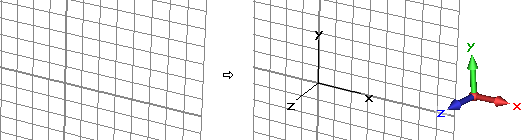
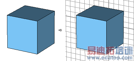
Working plane: With this flag, you may specify whether the drawing plane is visible or not (ALT+W).
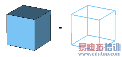
Wireframe: This flag indicates whether all shapes are visualized as simple wire models or as solid shaded objects (CTRL+W).
CST微波工作室培训课程套装,专家讲解,视频教学,帮助您快速学习掌握CST设计应用
上一篇:CST2013: Brick Creation Mode
下一篇:CST2013: Thermal Solver Problem Handling
CST培训课程推荐详情>>
 最全面、最专业的CST微波工作室视频培训课程,可以帮助您从零开始,全面系统学习CST的设计应用【More..】
频道总排行
- CST2013: Mesh Problem Handling
- CST2013: Field Source Overview
- CST2013: Discrete Port Overview
- CST2013: Sources and Boundary C
- CST2013: Multipin Port Overview
- CST2013: Farfield Overview
- CST2013: Waveguide Port
- CST2013: Frequency Domain Solver
- CST2013: Import ODB++ Files
- CST2013: Settings for Floquet B