- 易迪拓培训,专注于微波、射频、天线设计工程师的培养
CST2013: Face Constraints
录入:edatop.com 点击:
 Modeling: Tools
 Modify LocallyDefine Face Constraints...
In this mode, you may define constraints of picked faces. Those are properties of faces like a distance to other geometry or a radius of a cylindrical face.
To satisfy the constraint, local modifications are applied to the face(s) when you press 'Apply' or 'OK' (For a general description, check Face Modifications). If you continue modeling, it is not assured that these constraints stay valid.
You may remove defined face constraints in the Show Face Constraints dialog.
Note: This mode is intended for defining parameters that are to be used with sensitivity analysis (see Sensitivity Analysis Overview for more information). But it can also be useful for common modeling, to have an alternative way to define local modifications.
Continuing modeling on a shape with constraints attached will invalidate the constraints. Therefore, it is recommended to apply constraints that should be used with Sensitivity Analysis at the very end of the modeling process.
There are three types of face constraints:
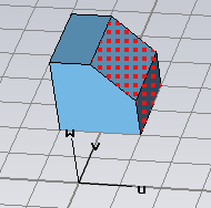
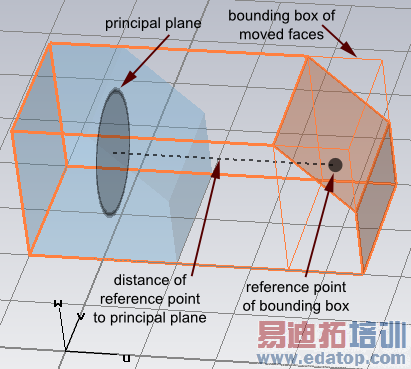
Set distance to plane
Of all picked faces, a bounding box is calculated. The center of this bounding box is used to define a distance to one of the three principal planes.
You may use the arrows to drag the bounding box around by mouse, or change the distance (and plane normal) in the dialog. To define a distance to an arbitrary plane, position the local coordinate system (WCS) to your likeness.
|
|
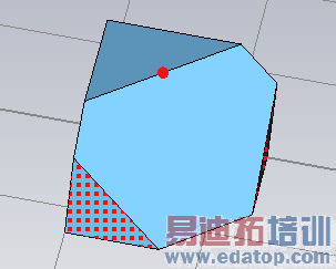
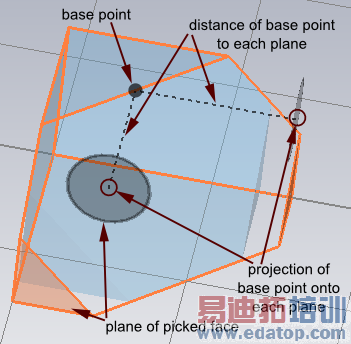
Set distance to point
We define the distance of a point to a planar face as the smallest distance to the plane that defines the surface of the planar face.
For every picked planar face, the distance to a base point is set to the given value. After this operation, all faces have the same distance to that point.
The base point is initialized as pick, if point picks exist, or the center of the last picked planar face is taken (that implies, that the initial distance of that face to the base point is zero). The dialog provides the possibility to set an arbitrary base point.
You may drag one of the picked faces around or use the dialog to specify the distance to the base point.
|
|
Set radius
All picked cylindrical faces are set to the entered radius. You may change the value by dragging the faces or entering a new radius.
Note: If you use the mouse to define a constraint on tiny details, snapping (rounding the constraint value) might become a problem. In that case, adjust the working plane settings in the Working Plane Properties dialog
Consider blends is explained in the article for Face Modifications.
Parametrize
You may set the new value (distance or radius) to a new parameter by simply clicking the Parametrize button. This is needed for the Sensitivity Analysis.
Sensitivity / Yield analysis
Parameters defined within this mode are valid for sensitivity analysis (as long as they are not used in any invalid operation)
CST培训课程推荐详情>>
 最全面、最专业的CST微波工作室视频培训课程,可以帮助您从零开始,全面系统学习CST的设计应用【More..】
频道总排行
- CST2013: Mesh Problem Handling
- CST2013: Field Source Overview
- CST2013: Discrete Port Overview
- CST2013: Sources and Boundary C
- CST2013: Multipin Port Overview
- CST2013: Farfield Overview
- CST2013: Waveguide Port
- CST2013: Frequency Domain Solver
- CST2013: Import ODB++ Files
- CST2013: Settings for Floquet B