- 易迪拓培训,专注于微波、射频、天线设计工程师的培养
CST2013: Wizard / Array Wizard
录入:edatop.com 点击:
Home: Macros MacrosWizardArray Wizard
This macro wizard is useful in designing planar arrays. Various operations are supported:
(1) Construct Finite Array from Single Element / Unitcell
(2) Simultaneous Excitation: Update Amplitude / Phase Distribution
(3) Perform Combine Results: Setup Amplitude / Phase Distribution and Execute
(4) Setup and Plot Farfield Array (using given array geometry and applying Amplitude / Phase Distribution as well as scan angle)
The following pictures illustrate some capabilities of this wizard.
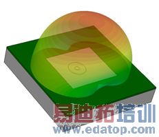
Single Element |
|
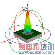
Single Element with Farfield-Array factor (4) |
|
Finite Array with different amplitude functions and scan angles incl. Construction Step(1) and either Simult.Exci (2) or Combine results (3) |
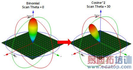
Since all these operations require similar input (number of elements, scan angle, amplitude/phase distribution for each port), this wizard remembers those settings, in order to easily change them or apply them to other operations in the array design process.
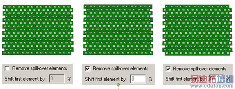
Grid Angle / Spill-over Elements
The Grid Angle specifies the angle in degrees between S1(x) and S2(y') axis, idenitical as used in the unit cell definition. The standard orthogonal rectangular array uses a grid angle of 90 degree.
In case you are using different grid angles, as eg Grid Angle = 60 degree as shown in the pictures below, the spill-over element settings will be activated: The “spill-over” elements can be removed or retained, by respectively checking and un-checking the Remove spill-over elements option. In addition, the Shift first element by __ % specification allows the user to intentionally create “spill-over” elements in the first row(s) as shown in the picture on the right.
Amplitude Weights
Various weighting functions are available, such as Uniform, Binomial, Cosine, Chevbyshev, Taylor, etc
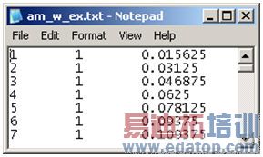
Also a userdefined ASCII table for the port amplitudes can be loaded, containing 3 colums: Port# / Mode# / Ampl, always separated by a TAB. Please note, that the phase distribution needs to be loaded in a separate phase ASCII file.
Load Phase Distribution...
Here a it is possible to load a userdefined ASCII table for the port phases. The format is identical to the amplitudes ASCII file. Phases have to be entered in degree.
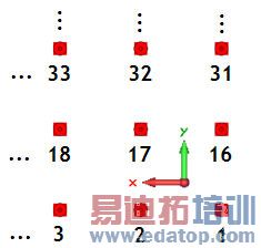
Number of Rows/Columns
When loading ASCII data for the port amplitude/phase, the numbering convention must be known.Ports are assumed to be numbered consecutively from Xmin to Xmax, and Ymin to Ymax. Thus, port 1 will be at (Xmin, Ymin) and will increment progressively until reaching (Xmax, Ymin). The next port number will be located at (Xmin, Ymin+1) and the cycle repeats until reaching (Xmax, Ymax), as shown here:
Frequency
The scan angles are transformed into phase delays between the ports at this Frequency. Consequently Results will be accurate for this frequency only
Specials...
Some more specific parameters concerning quantization error and polarization settings can be entered, which are explained in more detail below.
Number of Phase bits
Allows the user to specify the number of bits available to dictate the amount of phase shift precision (with an assumed total range of 360 degrees). For example, 4 bits corresponds to a precision of 22.5 degrees, thus the phase shift at each port is rounded to the nearest integer multiple of 22.5 degrees.
Number of Amplitude bits / Least Significant Bit (dB) / Maximum Attenuation (dB)
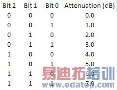
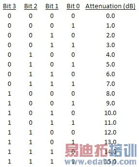
Similar to the Number of Phase bits, the Number of Amplitude bits allows the user to specify the number of bits available to dictate the amount of attenuation precision. However, the total range is not always the same and thus needs to be specified with the Least Significant Bit setting. For convenience, the maximum attenuation possible with the aforementioned specifications is displayed in the Maximum Attenuation (dB) box. The signal amplitude at each port will be rounded to the nearest attenuated value allowed with the given settings. A few example scenarios are shown in the table below:
3 bits, LSB = 0.5 dB, Max. Att. = 3.5 dB | 3 bits, LSB = 1 dB, Max. Att. = 7 dB | 4 bits, LSB = 1 dB, Max. Att. = 15 dB |
|
|
|

Note: if '0' is used for the Number of Phase bits/Number of Amplitude bits, the ideal case is implemented which corresponds to infinite phase shift/attenuation precision.
Progressive phase shift between element ports
This setting is only applicable if each element in the array has multiple ports. In this case you can specify a progressive phase shift between these ports in degrees. For example, if the array is made up of many, three port elements and 30 degrees is specified, the phase values at the ports would progress as follows:
Element 1 | Element 2 | Element 3 | ... |
Phase Port 1 = A | Phase Port 4 = B | Phase Port 7 = C | ... |
Phase Port 2 = A+30 | Phase Port 5 = B+30 | Phase Port 8 = C+30 | ... |
Phase Port 3 = A+60 | Phase Port 6 = B+60 | Phase Port 9 = C+60 | ... |
OK
Performs the chosen operation and applying all dialogues settings. In any case a history entry will be written as well as parameters are stored.
Cancel
Closes this dialog box without performing any further action.
Help
Shows this help text.
CST微波工作室培训课程套装,专家讲解,视频教学,帮助您快速学习掌握CST设计应用
上一篇:CST2013: Construct / Vias / Vias from Picks
下一篇:CST2013: 2D and 3D Field Results / - Power Flow 3D Mode
CST培训课程推荐详情>>
 最全面、最专业的CST微波工作室视频培训课程,可以帮助您从零开始,全面系统学习CST的设计应用【More..】
频道总排行
- CST2013: Mesh Problem Handling
- CST2013: Field Source Overview
- CST2013: Discrete Port Overview
- CST2013: Sources and Boundary C
- CST2013: Multipin Port Overview
- CST2013: Farfield Overview
- CST2013: Waveguide Port
- CST2013: Frequency Domain Solver
- CST2013: Import ODB++ Files
- CST2013: Settings for Floquet B