- 易迪拓培训,专注于微波、射频、天线设计工程师的培养
CST2013: Import Mentor Graphics?  ExpeditionTM PCB ASCII Files
录入:edatop.com 点击:
Modeling: Import/Export 2D/EDA FilesMentor Graphics Expedition
ExpeditionTM PCB of Mentor Graphics? Corporation is a widespread layout software for printed-circuit board (PCB) design. In order to be able to solve high-frequency problems of PCB signal and power integrity, CST DESIGN ENVIRONMENTTM offers capabilities for creating three-dimensional models from ExpeditionTM PCB layouts.
Important note:
Starting from version 2007.3, Mentor Graphics Expedition generates ASCII files only in encrypted format which is not readable directly by CST DESIGN ENVIRONMENTTM. A program for decrypting the files again can be obtained from Mentor Graphics corporation. Alternatively, you can import ODB++ files which can be generated by Mentor Graphics Expedition.
Creating the ASCII Database in ExpeditionTM PCB
In this part, we refer to ExpeditionTM PCB, Version 2005, Service Pack 1.
Creating the ASCII database is straightforward. By choosing FileExportASCII..., the following dialog appears.
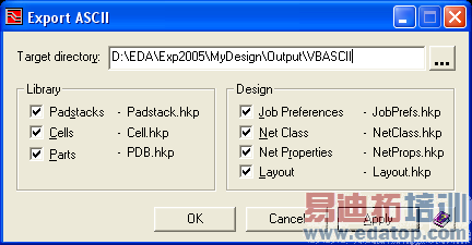
Make sure to check all ".hkp" files. Pressing the "OK" button will create the files in the specified target directory. For later import into CST DESIGN ENVIRONMENTTM you may copy the target directory (here "VBASCII") to a location of your choice and/or rename it.
Notes:
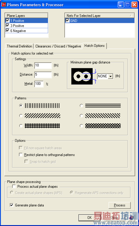
The treatment of so-called "plane shapes" of etch in ExpeditionTM PCB is based on shape outlines which are maintained as essential layout data. The filling of the shapes ("generated plane data") is performed in an additional step (via the ExpeditionTM PCB "plane processor") before manufacturing output. Please check that the plane data have been generated before creating the ASCII files: Choose PlanesPlane Parameters & Processor..., which opens the corresponding dialog box:
In this part, we refer to ExpeditionTM PCB, Version 2005, Service Pack 1.
The conductor layers containing plane shape objects are shown in the list "Plane Layers". When selecting a layer the list "Nets For Selected Layer" displays the nets that involve plane shapes. Please make sure that all layers in "Plane Layers", and -for each layer- all nets in "Nets For Selected Layer" are checked. Moreover, the option "Generate plane data" should be enabled. The options contained in the tabs "Thermal Definition" and "Clearances/Discard/Negative" can be left unchanged. The tab "Hatch Options" offers some control of the amount of plane data that will be generated: For too fine hatching, the plane data set will be unnecessarily large, leading to longer geometry processing upon 3D model creation. For fully covered shapes, a coarse, vertical (or horizontal), overlapping (i.e. Distance<Width) hatch pattern is recommended for better performance. Pressing the "Process" button will generate the plane data. Press "OK" to leave the dialog.
For further details on plane shape processing see the ExpeditionTM PCB documentation.
Importing and Exporting Models
CST微波工作室培训课程套装,专家讲解,视频教学,帮助您快速学习掌握CST设计应用
上一篇:CST2013: Import STEP
下一篇:CST2013: Shape Intersection Settings
CST培训课程推荐详情>>
 最全面、最专业的CST微波工作室视频培训课程,可以帮助您从零开始,全面系统学习CST的设计应用【More..】
频道总排行
- CST2013: Mesh Problem Handling
- CST2013: Field Source Overview
- CST2013: Discrete Port Overview
- CST2013: Sources and Boundary C
- CST2013: Multipin Port Overview
- CST2013: Farfield Overview
- CST2013: Waveguide Port
- CST2013: Frequency Domain Solver
- CST2013: Import ODB++ Files
- CST2013: Settings for Floquet B