- 易迪拓培训,专注于微波、射频、天线设计工程师的培养
CST2013: Mesh Properties
录入:edatop.com 点击:
 Simulation: Mesh
  Global Properties
Definition of cell size
For structured hexahedral meshes cell size can be defined independently in x, y or z direction. It is simply the length of the x, y or z edge of the cell. If the direction is not specified then the minimum or the maximum edge length is taken for minimum cell size definition or for maximum cell size definition respectively.
For unstructured meshes the cell size is interpreted as the average edge size around a mesh vertex. The size limits for unstructured meshes are not strict: the mesh generator may generate smaller or larger cells in order to improve the mesh quality.
Maximum cell
The settings in this group define the upper cell size limit in the mesh in order to provide some smallest necessary number of cells in the mesh in the absence of other refinements. For unstructured meshes the maximum cell size can be defined separately for the model and for the background. For structured hexahedral meshes the maximum cell size can be defined separately inside the model bounding box (near to model) and outside the model bounding box (far from model).
For high-frequency electromagnetic simulations the maximum cell size is often defined with respect to the wavelength in order to provide an optimal spatial sampling rate for the fields inside the structure. There are two possibilities to provide this wavelength-based definition of the maximum cell size:
Cells per wavelength: This value defines the upper limit to the cell size with respect to the wavelength. It also sets the spatial sampling rate for the signals inside your structure. This setting has a strong influence on both the quality of the results and the calculation time. Increasing this number leads to a higher accuracy, but also increases the total calculation time. The default value is chosen to provide a good compromise between the calculation time and the achievable accuracy.
Automatic (not available for some mesh types): In this mode, the cell size will be chosen automatically based on the selected solver and the solver settings.
There are types of simulations (low-frequency, thermal, etc...) where the maximum cell size is dictated by the size of geometric details of the structure. In this case it is possible to specify the maximum cell size as a Fraction of max model box edge. The maximum cell size is calculated by dividing the largest edge of the model bounding box by this number.
Note: If both Cells per wavelength (or Automatic) and Fraction of max model box edge are provided, then the setting which delivers the minimum size value will be taken to define the maximum mesh cell size. In this way structures that are much larger than the wave length will be refined according to Cells per wavelength in order to provide optimal field sampling. Structures that are small compared to the wave length will be refined according to Fraction of max model box edge in order to provide sufficient geometric resolution and optimal mesh quality.
Absolute value: Check this if you want to define an absolute value for the maximum cell size. In this case, Cells per wavelength and Fraction of max model box edge settings will be ignored.
Use same settings for near to and far from model: Check this if you want to use the same settings for maximum cell size calculation near to and far from model.
Minimum cell
This setting can be used in order to avoid overrefinement due to small geometric details such as thin regions or gaps (for hexahedral structured meshes) or very high curvatures (for unstructured meshes).
Note:
Minimum cell size can be overridden by the user by specifying refinement for model entities in the local mesh properties.
Small geometric details will always be resolved in the unstructured meshes.
Fraction of maximum cell near to model (or in the model): Minimum cell size is calculated by dividing the maximum cell size near to model (or in the model) by this number.
Absolute value in x, y, z: / Absolute value: Use this if you want to define an absolute value for the minimum cell size.
Use same settings in all three directions: Check this if you want to use the same absolute value in all three directions.
2D cutplane (only for planar meshes)
This group of settings allows to define the plane properties where the planar mesh is to be created.
Type: This settings defines if the plane represents a translational- or rotational-symmetry of the 3D domain.
Preview: This button allows to get a preview of the current settings
Depending on the chosen plane Type, the dialog elements are reconfigured and have different meanings:
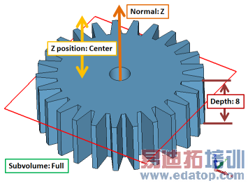
Translational | Rotational |
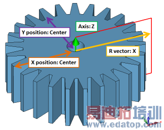
Normal: Defines the plane normal which is either aligned to the X-, Y- or Z-axis. | Axis: Defines the rotational axis which can be either the X-, Y, or Z-axis. |
X/Y/Z position: Defines the position of the plane on the chosen normal axis. It can be either aligned to the center of the whole structure or entered freely. | R vector: Defines the radial axis (X, Y, or Z) of the plane. |
Depth: This setting has no meaning for the mesh itself, but is used to compute integral values in a solver like the total energy. | X/Y/Z position: Defines the first transversal coordinate of the rotation axis. It can be either aligned to the center of the whole structure or entered freely. |
Subvolume: This control allows to define rotational periodicity in the translational plane. If "Circular" or the Edit button are selected a new dialog box opens up where the periodicity settings can be made. | X/Y/Z position: Defines the second transversal coordinate of the rotation axis. It can be either aligned to the center of the whole structure or entered freely. |
Translational mesh preview with settings |
Rotational mesh preview with settings |
In case of uncertainty it is always advisable to use the preview functionality in order to get a good impression where the meshing plane will be positioned.
Meshing method (only for unstructured meshes)
Choose between Default (surface based) and Octree (Volume based) methods.
Refinement settings (only for Multilayer mesh type)
Edge Refinement: In this drop-down list you may control the edge refinement for the multi-layer mesh. When you select None the edge refinement is switched off, in the other cases the edge refinement is performed and you may choose the edge refinement value. Either you specify the value as fraction of the wave length, as fraction of the maximal port edge length or as an absolute value. The edge refinement value determines the maximal offset as well as the minimal offset for each edges. The minimal offset is calculated as the tenth of the edge refinement value. If a fraction of maximal port edge length is chosen a characteristic width of the existing conductors will be calculated.
Statistics
These statistics are mere information and cannot be edited.
For hexahedral mesh (i.e. Hexahedral and Hexahedral TLM):
Smallest cell: The smallest cell edge.
Largest cell: The largest cell edge.
Number of cells: Total number of mesh cells. This is directly connected to the simulation time and the amount of memory required.
Nx / Ny / Nz: Number of mesh lines in coordinate direction x, y and z respectively.
For unstructured mesh (i.e. Tetrahedral, Surface and Multilayer):
Minimum edge length: The length of the shortest mesh edge.
Maximum edge length: The length of the longest mesh edge.
Tetrahedrons: The number of mesh cells.
Minimum quality: The minimum of all mesh cell quality values.
Maximum quality: The maximum of all mesh cell quality values.
Average quality: The average of all mesh cell quality values
Note:
The quality of a tetrahedron measures how good its shape matches the shape of an ideal, equilateral tetrahedron. It is defined by the expression
 ,
,
where rin is the inradius of the tetrahedron and rcirc the circumradius. The factor 3 is a scaling factor, such that the quality is positive and less or equal to one. Low quality values indicate degenerated mesh cells, which may have a negative impact on the convergence.
OK
Accepts the changes and closes the dialog. If changes were made, the mesh will be updated.
Apply
Stores the current settings. The dialog box open remains open.
Cancel
Closes this dialog box without performing any further action.
Update / Force LF Mesh / Force HF Mesh
Update: In cases where the determination of the mesh needs some time (staircase mesh for instance) it is not updated automatically by the "Apply" or the "OK" button. Press this button to force the mesh to be updated.
Force LF Mesh: / Force HF Mesh: If the problem type has been changed from "High Frequency" to "Low Frequency" or vice versa you will be asked if the mesh should be updated according to the new problem class. Pressing this button may delete existing results.
Specials...
This button leads to a dialog box, that allows you to define advanced mesh generation settings.
Help
Shows this help text.
See also
Mesh View, Frequency Range. Which mesh to use, Circular Subvolume
CST培训课程推荐详情>>
 最全面、最专业的CST微波工作室视频培训课程,可以帮助您从零开始,全面系统学习CST的设计应用【More..】
频道总排行
- CST2013: Mesh Problem Handling
- CST2013: Field Source Overview
- CST2013: Discrete Port Overview
- CST2013: Sources and Boundary C
- CST2013: Multipin Port Overview
- CST2013: Farfield Overview
- CST2013: Waveguide Port
- CST2013: Frequency Domain Solver
- CST2013: Import ODB++ Files
- CST2013: Settings for Floquet B