- 易迪拓培训,专注于微波、射频、天线设计工程师的培养
CST2013: Farfield Calculation of Antenna Arrays
录入:edatop.com 点击:
 Farfield Plot: Plot Properties
  Farfield Array
This dialog offers the possibility to apply the pattern multiplication to a calculated farfield monitor to obtain the corresponding result for a specific antenna array built of identical elements:
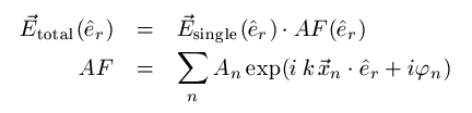
The application of an array factor provides only an approximation to the self-consistent calculation of an entire array. In particular, it does not guarantee energy conservation: The radiated power of the entire array may well exceed the total input power of the array. Therefore a final scaling of the array farfield is applied which sets the array radiation efficiency to the radiation efficiency of the single element. A significant rescaling of the array farfield indicates a poor performance of the array factor multiplication due to strong mutual coupling among the array elements. Please consider using periodic boundary conditions in this case to obtain a more accurate model of the nearfield coupling to neighboring array elements.
The picture below shows the abstract array pattern of six identical elements, each representing a single patch antenna as shown on the left side
Single Patch Antenna |
| Array Pattern of Six Identical Elements |
|
|
|
In the farfield array dialog box a general rectangular array can easily be defined by entering the respective number of elements as well as the space- and phaseshift in each coordinate direction, whereby the reference point of the array is defined as the physical center of the complete grouping structure. The obtained antenna list can be modified or extended by editing the properties of single array elements and the complete result is visualized alternatively in polar, Cartesian, 2D or 3D representation, correspondent to the Plot Type settings in the Farfield Plot dialog.
Rectangular array
Activate this check button to define a rectangular antenna array (linear: 1D; planar: 2D; cubic: 3D). Afterwards, you still have the possibility to modify the resulting array list by changing the element's settings or by removing or adding specific elements.
Edit antenna list
This check button offers the possibility of entering an antenna array manually or of modifying a previously calculated antenna list while the input facilities for rectangular arrays are disabled. In the list, it is possible to modify or delete existing antenna elements or create some new ones and add them to the list.
Rectangular array frame
A complete rectangular array may be calculated automatically just by defining the following values. Note that this frame is enabled when the corresponding check button above is activated. The array setup uses automatically the unit cell geometry and phasing if unit cell or periodic boundary conditions are active.
Direction: Specifies the orientation of the rectangular array.
Number: Defines the number of single antenna elements in each coordinate direction.
Spaceshift: Defines the constant space shift between two antenna elements in the respective coordinate direction.
Phaseshift: Defines the constant phase shift between two antenna elements in the respective coordinate direction.
Update antenna list: Evaluates the complete antenna list of the rectangular array defined by the given values and shows it in the listbox below. The single antennas are characterized by their location in space (x, y, z) as well as by their amplitude and phase information.
Antenna list frame
Displays the current antenna list of the array pattern. If the list is activated single antenna elements can be modified, deleted or created in order to define an arbitrary array pattern. Note that this frame is enabled when the corresponding check button above is activated.
No.: A unique number is assigned to each antenna array element.
X,Y,Z: These values show the spatial location of each array element.
Amplitude: Shows the amplitude of each array element. Using the automatic calculation for a rectangular array the default for the amplitude of all elements is one.
Phase: Shows the given phase information of each array element.
Modify...: Opens a dialog window for changing the position, the amplitude or the phase properties of a selected antenna element.
Add...: Offers the possibility to add a new single antenna element to the given array list by defining its position as well as the amplitude and phase properties.
Delete: Deletes a selected element of the given antenna list.
OK
Confirming the OK button will plot the farfield result of the current antenna list. If the editing possibility is activated, the momentarily shown list is used for calculation ignoring the settings of the Rectangular Array dialog.
Cancel
Leaving the Farfield Array dialog without saving any changes. The previously made settings are maintained.
Help
Shows this help text.
Example
Farfield polar plot of a l/2-dipole antenna. |
| Farfield polar plot of a linear array with two elements of the dipole antenna shown left exhibiting a spaceshift of l/4 and a phaseshift of 90 degrees. |
|
|
|
CST培训课程推荐详情>>
 最全面、最专业的CST微波工作室视频培训课程,可以帮助您从零开始,全面系统学习CST的设计应用【More..】
频道总排行
- CST2013: Mesh Problem Handling
- CST2013: Field Source Overview
- CST2013: Discrete Port Overview
- CST2013: Sources and Boundary C
- CST2013: Multipin Port Overview
- CST2013: Farfield Overview
- CST2013: Waveguide Port
- CST2013: Frequency Domain Solver
- CST2013: Import ODB++ Files
- CST2013: Settings for Floquet B