- 易迪拓培训,专注于微波、射频、天线设计工程师的培养
CST2013: Farfield Plot – Axes
录入:edatop.com 点击:
 Farfield Plot: Plot Properties
  Properties Axes
Rotating the coordinate system
In some cases, you may want your farfield’s main lobe to be in a special direction (i.e., Phi = 0 and Theta = 90 degrees) other than those resulting from the default settings. Then, you will have to specify new origins for Theta and Phi. For example, this might be helpful to partly visualize the vertical and horizontal polarization of a farfield calculation.
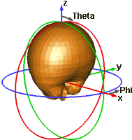
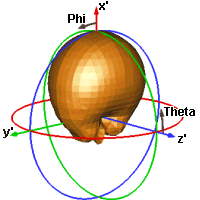
As an example, assume your main lobe is in the z-direction. It will therefore be in direction Theta = 0 by default. You, however, want it to be in direction Phi = 0 and Theta = 90. Therefore, you must change the origin for Theta from (0, 0, 1) to (1, 0, 0) and the origin for Phi (1, 0, 0) to (0, 0, 1).
In 3D plots, the new coordinate axes x’, y’ and z’ will be displayed for better orientation.
|
|
old settings Z’=Z=(0,0,1), X’=X=(1,0,0) | new settings Z’=(1,0,0), X’=(0,0,1) |
Axes type frame
Specifies the alignment of the farfield coordinate system. The following rotation types are available:
XYZ coordinates | Alignment with the global coordinate system. |
User defined | User defined alignment using the orientation specified by Thetastart and Phistart. |
Main lobe alignment | Aligns the coordinate system with the main lobe direction (z') and the Polarization vector (y'). |
Current WCS | The coordinate system is set to the current wcs. |
Start for theta (z'-axis) frame
X / Y / Z: Here, you may set the origin for Theta. You may enter any numbers; the resulting vector will be normalized to 1 later. Only, you have to make sure that it is not parallel to the vector set as x’-axis (origin for Phi). These values only apply if the axes type is set to User defined.
Start for phi (x'-axis) frame
X / Y / Z: Here, you may set the origin for Phi. You may enter any numbers; the resulting vector will be normalized to 1 and orthogonalized to the z’-axis later. However, you have to make sure that it is not parallel to the vector set as z’-axis (origin for Theta). These values only apply if the axes type is set to User defined.
Polarization vector (y'-axis) frame
X / Y / Z: Enter here the coordinates for the y'-axis in global cartesian coordinates. These values only apply if the axes type is set to Main lobe alignment.
Coordinate system frame
Different kind of field components can be plotted with regard to different coordinate systems. You may select the coordinate system here. You may choose among the Spherical, Ludwig 2 Azimuth over Elevation, Ludwig 2 Elevation over Azimuth and the Ludwig 3 coordinate system. See farfield view for more information.
Polarization frame
Three different polarizations are available for each coordinate system: linear, circular and slant. The slant polarization requires the additional specification of the slant angle. See farfield overview for more information.
OK
Stores the current settings and closes the dialog box. Depending on the new settings, a new plot of the farfields will be calculated. The calculation can be aborted by pressing the Abort button.
Apply
Stores the current settings leaving the Farfield Plot tab sheet opened. Depending on the new settings, a new plot of the farfields will be calculated. The calculation can be aborted by pressing the Abort button.
FF View / Preview
Use this button to switch between farfield view and coordinate system preview. The latter hides the farfield and shows only the structure in respect to the defined coordinate system. In addition, Bistatic RCS results visualize the exciting plane wave. Leaving the preview mode with pressing Close restores axes, origin, and mirror plane settings.
Abort
Aborts the current calculation. Note that the last plot has been deleted. You will have to calculate a new plot by making the appropriate settings and pressing the OK or Apply button again.
Close
Closes this dialog box without performing any further action.
Help
Shows this help text.
See also
Farfield Overview, Farfield View, Color Ramp, Farfield Plot
Farfield Plot Dialog Pages: General, View, Plot Mode, Origin, Array, Phase Center, Decoupling Plane
CST培训课程推荐详情>>
 最全面、最专业的CST微波工作室视频培训课程,可以帮助您从零开始,全面系统学习CST的设计应用【More..】
频道总排行
- CST2013: Mesh Problem Handling
- CST2013: Field Source Overview
- CST2013: Discrete Port Overview
- CST2013: Sources and Boundary C
- CST2013: Multipin Port Overview
- CST2013: Farfield Overview
- CST2013: Waveguide Port
- CST2013: Frequency Domain Solver
- CST2013: Import ODB++ Files
- CST2013: Settings for Floquet B