- 易迪拓培训,专注于微波、射频、天线设计工程师的培养
CST2013: Farfield Plot – Phase Center
录入:edatop.com 点击:
 Farfield Plot: Plot Properties
  Properties Phase Center
The phase center is calculated using the phase of the phi or theta component of the electric field. The calculation is limited by an angle around the z'-axis. The z'-axis may be either the main lobe or a user defined axis as entered in the Farfield Plot - Axes page. The phase center is calculated from phase values in two planes for a constant reference distance. One plane is defined by the polarization vector (y'-axis) and the z'-axis called E-Plane. The other plane is defined by the x'-axis and the z'-axis perpendicular to the E-Plane called H-Plane. Depending on the selected plane the phase center will be calculated for the E-Plane, H-Plane or for both planes. If both planes are calculated the phase center location is averaged afterwards.
The results of the phase center calculation will be displayed in the lower left corner of the 3D farfield plot in global cartesian coordinates. In addition, the maximum standard deviation "Sigma" of the phase center location is shown. To validate the results set the origin of the farfield to the phase center location in the Farfield Plot - Origin page and select the phase of the selected field component in the Navigation Tree to get a 3D plot of the phase.
Testing the Phase center result: You may check the behavior of phase by entering the phase center result coordinates as new Box origin and then plotting the phase. Because the spherical unit vector theta changes its direction in the most interesting point around the z' axis, the E-theta phase has a 180 degree phase jump at theta = 0. It is therefore recommended to switch to the Ludwig3 representation of the farfield to check the constant field around the z' axis (around theta = 0).
Calculate phase center
Activate to enable the calculation of the phase center.
E-Field component frame
Theta / Phi / Boresight: Select here the farfield component that is used to calculate the phase center. Theta and phi use the phase of the corresponding spherical components. Boresight evaluates the farfield in +z' direction, extracts the polarization vector from this field and uses this reference to calculate the phase.
Angular limit around z’ axis frame
Angle: Enter here the angle a in degrees that limits the area around the z’ axis that is used to calculate the phase center.
E-plane | H-plane |
|
|
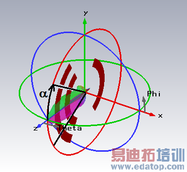
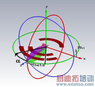
Note: The settings for the z’ axis can be modified using the Farfield Plot Special Settings – Axes page.
Plane frame
Select here the plane used for the phase center calculation. If both planes are selected (Both), the calculated phase center is the average of the phase center for the E-plane and H-plane.
Show phase center
Visualizes the phase center with an ellipses indicating the error bounds. Calculation planes and angular limit are also displayed to ease the verification of the calculation parameters.
OK
Stores the current settings and closes the dialog box. Depending on the new settings, a new plot of the farfields will be calculated. The calculation can be aborted by pressing the Abort button.
Apply
Stores the current settings leaving the Farfield Plot tab sheet opened. Depending on the new settings a new plot of the farfields will be calculated. The calculation can be aborted by pressing the Abort button.
FF View / Preview
Use this button to switch between farfield view and coordinate system preview. The latter hides the farfield and shows only the structure in respect to the defined coordinate system. In addition, Bistatic RCS results visualize the exciting plane wave. Leaving the preview mode with pressing Close restores axes, origin, and mirror plane settings.
Abort
Aborts the current calculation. Note that the last plot has been deleted. You will have to calculate a new plot by making the appropriate settings and pressing the OK or Apply button again.
Close
Closes this dialog box without performing any further action.
Help
Shows this help text.
See also
Farfield Overview, Farfield View, Color Ramp, Farfield Plot
Farfield Plot Dialog Pages: General, View, Plot Mode, Axes, Origin, Array, Decoupling Plane
CST培训课程推荐详情>>
 最全面、最专业的CST微波工作室视频培训课程,可以帮助您从零开始,全面系统学习CST的设计应用【More..】
频道总排行
- CST2013: Mesh Problem Handling
- CST2013: Field Source Overview
- CST2013: Discrete Port Overview
- CST2013: Sources and Boundary C
- CST2013: Multipin Port Overview
- CST2013: Farfield Overview
- CST2013: Waveguide Port
- CST2013: Frequency Domain Solver
- CST2013: Import ODB++ Files
- CST2013: Settings for Floquet B