- 易迪拓培训,专注于微波、射频、天线设计工程师的培养
CST2013: Excitation Selection
录入:edatop.com 点击:
 Simulation: Solver
  Start Simulation Time Domain Solver Excitation list
This dialog offers the possibility to define a specific selection of port modes for the time domain solver pic solver excitation. The selected modes can either be excited one after another or simultaneously considering different amplitudes, phase resp. time shifts and excitation signals. Keep in mind that no S-Parameter calculation is possible for a simultaneous simulation, but corresponding normalized DFT spectra will be plotted in these cases.
Excitation list
Here, all occurring excitations (port modes as well as current distributions) are listed and can be chosen for excitation by activating the respective check button. These buttons are highlighted in light blue if the corresponding port mode has already been calculated successfully.
If a simultaneous excitation is activated, the specific settings for each excited port mode can be defined in this list. It is possible to enter different amplitude values in combination with either different time shifts or alternatively, phase shift values in respect to a defined reference frequency. All these settings are applied to arbitrary time signals that can be selected from the previously-defined excitation signals. All these values are referred to a reference signal with amplitude one (1/sqrt(watt)) and zero phase shift for a waveguide port (see reference value and normalizing for details). The corresponding excited power rms value is evaluated as amplitude^2 / 2 and shown in the list frame.
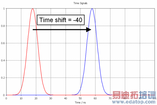
Note: A positive value for the time shift means that the time signal is shifted to the left. in order to define a time delay one must set a negative time shift.
Set all
Pressing this button selects all occurring port modes in the excitation list.
Set none
Pressing this button deselects all occurring port modes in the excitation list.
Simultaneous excitation frame
Activate: This check button activates the simultaneous port mode excitation in accordance with the settings made in the excitation list above.
Automatic labeling: This check button enables or disables the automatic labeling for the simultaneous excitation signal. The automatically generated label consists of the selected port mode combination including the specific amplitude, the phase shift value with corresponding reference frequency, the time shift value and the used excitation signal name. Note that the signal name will be skipped in case the global reference signal is chosen.
Label: Displays the label for the simultaneous excitation signal either as a user input or generated automatically.
List: This list shows all previously defined labels belonging to combined excitation signals, including the inputs made in the Combine Results dialog as a post processing step.
Please note, that in case of a simultaneous excitation a usual S-Parameter calculation is not possible anymore and so-called F-Parameters and active S-parameters are given as simulation results. More information about these result plots is given on the Reference Value and Normalizing page.
Excitation offset frame
The temporal shift between the excitation signals of simultaneous stimulated ports can be characterized either by a time shift or a phase shift. The phase shift setting requires a phase reference frequency: The phase values defined in the excitation list above are converted into corresponding time shifts for the time signals by use of this reference frequency. For example, a broadband phase shift of 180 degrees can be achieved by: amplitude = &endash;1 and phase = 0.
OK
Accepts the input and closes the dialog.
Cancel
Closes this dialog box without performing any further action.
Help
Shows this help text.
Waveguide Ports, Discrete Ports, Current Distributions
CST微波工作室培训课程套装,专家讲解,视频教学,帮助您快速学习掌握CST设计应用
上一篇:CST2013: Eigenmode Solver Specials (AKS)
下一篇:CST2013: Optimizer
CST培训课程推荐详情>>
 最全面、最专业的CST微波工作室视频培训课程,可以帮助您从零开始,全面系统学习CST的设计应用【More..】
频道总排行
- CST2013: Mesh Problem Handling
- CST2013: Field Source Overview
- CST2013: Discrete Port Overview
- CST2013: Sources and Boundary C
- CST2013: Multipin Port Overview
- CST2013: Farfield Overview
- CST2013: Waveguide Port
- CST2013: Frequency Domain Solver
- CST2013: Import ODB++ Files
- CST2013: Settings for Floquet B