- 易迪拓培训,专注于微波、射频、天线设计工程师的培养
CST2013: Boundary Conditions - Unit Cell
录入:edatop.com 点击:
 Simulation: Settings
  Boundaries Unit Cell
The Unit Cell boundary condition virtually repeats the modeled structure periodically in two directions up to infinity. This dialog box allows you to define the periodicity of such an infinite array.
Note: Unit cell boundary conditions apply to the general purpose frequency domain solvers.
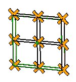
The picture on the right shows how a simple model is visualised in the main plot window before any Unit Cell boundary condition is applied.
As soon as the "Boundary Conditions" dialog box is open and a boundary has been set to "Unit Cell," the basic structure (the unit cell) will be plotted in its periodic expansion. The Unit Cell boundary condition expands the model always in the X-Y-plane of the global coordinate system. | |

Fit unit cell to bounding box
If this radio button is switched on, the model will be repeated at its bounding box borders (see picture above).
S1(x) / S2'(y) periodicity, Grid angle
S1(x) and S2'(y) define the distances between two neighbouring unit cells in two different coordinate directions. The spatial relation between these two axes is defined by the value of "Grid angle". S1(x) is aligned to the x-axis of the global coordinate system.
Note: The hexahedral frequency domain solver needs a value of 90 degrees for "Grid angle." |
|

OK
Accepts your settings and leaves the dialog box.
Cancel
Closes this dialog box without performing any further action.
Help
Shows this help text.
See also
Frequency Domain Solvers
Boundary Conditions: Boundaries, Symmetry Planes, Phase Shift/Scan Angle, Boundary Temperature
CST微波工作室培训课程套装,专家讲解,视频教学,帮助您快速学习掌握CST设计应用
上一篇:CST2013: Asymptotic Solver Defaults
下一篇:CST2013: Define Result Template Goal
CST培训课程推荐详情>>
 最全面、最专业的CST微波工作室视频培训课程,可以帮助您从零开始,全面系统学习CST的设计应用【More..】
频道总排行
- CST2013: Mesh Problem Handling
- CST2013: Field Source Overview
- CST2013: Discrete Port Overview
- CST2013: Sources and Boundary C
- CST2013: Multipin Port Overview
- CST2013: Farfield Overview
- CST2013: Waveguide Port
- CST2013: Frequency Domain Solver
- CST2013: Import ODB++ Files
- CST2013: Settings for Floquet B