- 易迪拓培训,专注于微波、射频、天线设计工程师的培养
CST2013: TDR (Time Domain Reflectometry)
Post Processing: Result Templates Template Based Post Processing
 Time Signals
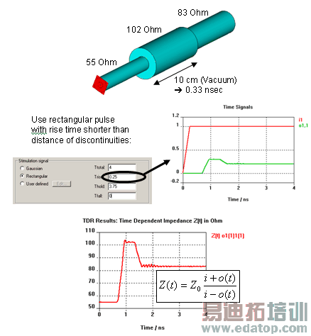
This template evaluates the impedance profile along a TEM or similar structure based on the reflected time signals at a port (mode).
TDR computation (Time Domain Reflection) is well known from measurement, where TDR is the only possibility to ”look into a structure” and locate mismatches. Typically TDR is applied to TEM structures such as connectors or IC packages designed to have minimum return loss. CST MWS with its transient solver is ideally suited for this task, since TDR pulses have to be short in time (to be able to resolve discontinuities in space) and thus extremely broadband.
The TDR can be calculated with two kind of excitations: 1) step time signal or 2) Gaussian time signal. The template automatically recognizes the signal type and switches between the different TDR calculation methods 1) and 2):
1) Step time signal
A rising rectangular pulse as excitation signal is the typical pulse for TDR evaluation. It has however the disadvantage, that the energy is not decaying (time signal never stops) as well as that the frequency data such as S-Parameters has some "undefined frequencies" due to zero-amplitudes in the excitation spectrum. Both disadvantages do not appear when exciting with a gaussian pulse. That's why using a gaussian pulse according to method 2) is recommended.

”Z(t)” is the TDR impedance, ”Z0 ”is the port line impedance, ” i” is the amplitude of the input step signal. ”o(t)” is the reflection signal.
Note: In order to resolve the stimulated highest frequencies in time and space by the discretization, you should choose the upper frequency limit to at least 1/Trise.

2) Gaussian time signal
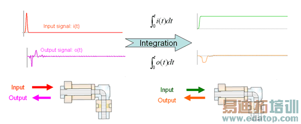
When using a gaussian pulse, the TDR is calculated from the time integral of the pulse, which again is the well-known (smooth) step function.


”Z(t)” is the TDR impedance, ”Z0 ”is the port line impedance, ” i(t)” is input Gaussian signal . ”o(t)” is the reflection signal.
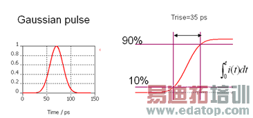
Note: The rise time in this case correlates to the upper limit of the frequency band. The frequency range should be adjusted to fmin=0, fmax=”0.876 / rise time”. The rise time is the 10% to 90% rising time of a corresponding step signal, which is the result of an integrated gaussian pulse.
Example: if the rise time should be 35 ps, then fmax = 0.876/35ps = 25.14GHz. You can see the Gaussian pulse below. The integral of this pulse gives you the step signal with 35ps 10% to 90% rise time.
|
|
Gaussian Pulse options
This frame contains two options, which only apply to the Gaussian pulse. Both options should not be used in case of a step type input signal.
Shift T_0(TDR) to T_50%(Pulse)
This option shifts the TDR response in time: The TDR plot then starts at t=0, when the input pulse for the TDR computation reached 50% of its maximum.

The pictures illustrate the shift in time, when the Gaussian Pulse is used. For a step pulse, this can be done manually using e.g. the 1D Result from 1D Result template.
The shift option is generally used in order to avoid the time before the pulse and the return signal establishes. This is most useful, if you want to compare the TDR to the measurement or cross probe from the TDR to the device under test.
Note: When using the TDR from S-Parameters calculation, the TDR is automatically shifted in time to comply with this setting.
Calculate Reflection Factor
This option, when checked, calculates the reflection factor over time instead of the time domain reflectometry (TDR). The reflection factor is bound between -1 and +1. Therefore even for an open transmission line, the reflection factor stays within these limits – in contrast to the TDR, which is infinite in this case. The reflection factor is also useful, if the structure needs to be optimized, hence the reflection minimized.
OK
This button completes the setup of the template. The new entry will be added to the list of templates which are executed automatically after each run. The default name of the template is set according to the settings, as long the name has not been changed manually.
Cancel
Aborts the setup of the template and closes this dialog box without performing any further action.
Help
Shows this help text.
CST微波工作室培训课程套装,专家讲解,视频教学,帮助您快速学习掌握CST设计应用
上一篇:CST2013: Construct / Superconducting Cavity
下一篇:CST2013: General / Load 1D Data File (project and external)
 最全面、最专业的CST微波工作室视频培训课程,可以帮助您从零开始,全面系统学习CST的设计应用【More..】
频道总排行
- CST2013: Mesh Problem Handling
- CST2013: Field Source Overview
- CST2013: Discrete Port Overview
- CST2013: Sources and Boundary C
- CST2013: Multipin Port Overview
- CST2013: Farfield Overview
- CST2013: Waveguide Port
- CST2013: Frequency Domain Solver
- CST2013: Import ODB++ Files
- CST2013: Settings for Floquet B


