- 易迪拓培训,专注于微波、射频、天线设计工程师的培养
CST2013: Farfield&Antenna / Bandwidth Potential
录入:edatop.com 点击:
Result Templates Template Based Post Processing
This template calculates the maximal bandwidth of an antenna that can be achieved by an ideal two component matching circuit. This is done for every frequency point and therefore gives an indication of how well the bandwidth of an antenna can be improved by suitable matching components.
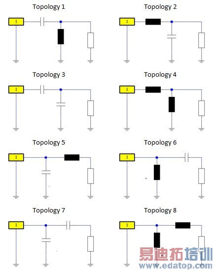
For this purpose eight different topologies are tested (see picture below). Depending on the position in the Smith chart for each frequency point, either two or four topologies will allow a perfect match. The one with the widest bandwidth at the defined matching level is recorded.
The user can choose whether to display the absolute bandwidth (in project units) or relative bandwidth related to the evaluation frequency. The bandwidth will typically be located asymmetrically around the evaluation frequency. A checkbox allows the user to reduce it to a symmetric bandwidth which is double the smaller side of the bandwidth range. It should be remembered that the maximum bandwidth may also be limited by the global simulation frequency settings f_min and f_max, so these should be chosen to be wide enough.
If several ports and modes are defined, it can be chosen which one to use for the evaluation. If an AR filter estimation was used to increase the accuracy of poorly converged S-Parameters, it is recommended to use the AR-filtered results.
The Bandwidth Potential result template always stores either the full bandwidth potential or the symmetric bandwidth potential as a table result, which can be recorded during parameter sweeps or be used to define optimization goals.
Additionally, the following information is recorded in the 1D result folder under "1D Results / Bandwidth Potential":
• Full and symmetric bandwidth potential
• Optimal topology for full and symmetric case for every evaluated frequency. The numbers 1-8 refer to the topologies shown below.
• The number of possible ideal two-component matching circuits (either two or four).
• The values of the perfect matching circuit with the widest bandwidth for every evaluated frequency.
The topologies:
CST微波工作室培训课程套装,专家讲解,视频教学,帮助您快速学习掌握CST设计应用
上一篇:CST2013: EMC / Calculate Broadband EMC-Norm
下一篇:CST2013: 2D and 3D Field Results / SAR Result
CST培训课程推荐详情>>
 最全面、最专业的CST微波工作室视频培训课程,可以帮助您从零开始,全面系统学习CST的设计应用【More..】
频道总排行
- CST2013: Mesh Problem Handling
- CST2013: Field Source Overview
- CST2013: Discrete Port Overview
- CST2013: Sources and Boundary C
- CST2013: Multipin Port Overview
- CST2013: Farfield Overview
- CST2013: Waveguide Port
- CST2013: Frequency Domain Solver
- CST2013: Import ODB++ Files
- CST2013: Settings for Floquet B