- 易迪拓培训,专注于微波、射频、天线设计工程师的培养
CST2013: Farfield Source File Format
录入:edatop.com 点击:
File format
The farfield source file may contain several linearly scaled farfield patterns (E_theta and E_phi) in spherical coordinates for phi = 0...360 degrees and theta = 0...180 degrees or several sets of electric and magnetic multipoles, depending on the file header. The frequency and optional power values must be specified for each frequency sample in the header as well.
Files can be created in the Farfield Plot – General dialog from any farfield result, though any properly formatted data (e.g. measurements) may be used.
The specified file must contain the following information (See the examples below):
1. Version number, currently 3.0
2. Data type information. Supported formats are "Farfield" and "Multipoles".
3. Number of frequency samples.
4. Alignment: Position coordinates in meters, z-Axis and x-Axis of the antenna coordinate frame.
5. Frequency sample information. One entry for each sample is required:
Radiated power
Accepted Power
Stimulated power
Frequency in Hz
The power information for the farfield excitation is expected in Watt (mean power). A new line for each value is expected.
If this information is not available:
a) If the Radiation Efficiency and the Total Efficiency are known the radiated power can be set to one and accepted power should be set to Radiation Efficiency = -1 and stimulated power should be set to Total Efficiency = -1. The power information will then be calculated automatically.
b) If no power information is available please set the values to -1. In this case the "Radiated power" will be calculated automatically and "Accepted power" and "Stimulated power" will be set to this value as well (i.e. the farfield source is assumed to be a perfect antenna).
The following data block depends on the specified format. "Farfield" requires:
6a. Total number of phi samples and total number of theta samples (both in one line separated by a blank or tab)
7a. Field pattern for all angles including phi =360 degrees
Phi, Theta, Re(E_Theta), Im(E_Theta), Re(E_Phi), Im(E_Phi)
The observation angles are expected as an ascending sequence of theta-scans.
The field pattern is equivalent to the linearly scaled farfield with reference distance of 1m without phase factor. The pattern can be calculated from the farfield as follows:.
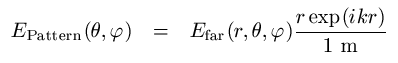
It is recommended to use a step size with rather small value (e.g. 1 degree) to ensure high accuracy of the simulation where the farfield source is used. Only equidistant sampling is supported
The spherical coordinate system is used.
The "Multipoles" format requires:
6b. Total number of multipole entries
7b. Multipole data. Each line must contain Degree, Order, Re(a), Im(a), Re(b), Im(b). The electric multipole coefficients a are expected in V/m, the magnetic coefficients b in A/m. A special ordering of the multipoles is not required.
Several data blocks may be specified according to the number of frequency samples given in the header.
Lines starting with // will be ignored.
Version History
Version | Farfield Data | Multipole Data | Description |
3.0 | Example | Example | Broadband source definition added |
2.1 | Example | Example | Source position and alignment added |
2.0 | Example | Example | Multipole data introduced |
1.1 | Example |
| First farfield source file definition |
1.0 |
|
| No longer supported |
CST微波工作室培训课程套装,专家讲解,视频教学,帮助您快速学习掌握CST设计应用
上一篇:CST2013: Multipin Port Overview
下一篇:CST2013: Network Parameter Extraction Overview
CST培训课程推荐详情>>
 最全面、最专业的CST微波工作室视频培训课程,可以帮助您从零开始,全面系统学习CST的设计应用【More..】
频道总排行
- CST2013: Mesh Problem Handling
- CST2013: Field Source Overview
- CST2013: Discrete Port Overview
- CST2013: Sources and Boundary C
- CST2013: Multipin Port Overview
- CST2013: Farfield Overview
- CST2013: Waveguide Port
- CST2013: Frequency Domain Solver
- CST2013: Import ODB++ Files
- CST2013: Settings for Floquet B