- 易迪拓培训,专注于微波、射频、天线设计工程师的培养
HFSS15: Uniform Applied Bias Fields
录入:edatop.com 点击:
The applied DC bias that causes ferrite saturation is always in the positive z direction of the tensor coordinate system. Initially the tensor coordinate system is assumed to be aligned with the fixed coordinate system; the tensor’s z-axis is the same as the model’s z-axis. To model other directions of applied bias, the permeability tensor must be rotated so that its z-axis lies in another direction on the fixed coordinate system. This is accomplished by specifying the rotation angles about the axes when you assign a magnetic bias source to a model surface.
The rotation angles should be defined in the Magnetic Bias Source dialog box in such a way that the tensor coordinate system is obtained in the following manner:
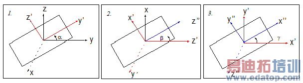
1. Rotating the tensor coordinate system by a degrees (from the X Angle) around the fixed x-axis.
2. Rotating the resulting tensor coordinate system by b degrees (from the Y Angle) around the new y-axis.
3. Rotating the new tensor coordinate system by g degrees (from the Z Angle) around the new z-axis.
This concept is illustrated in the following graphic. In the first panel, the permeability tensor is rotated a degrees about the x-axis. In the second panel, the tensor is rotated b degrees about the y'-axis (the new y-axis). In the third panel, the tensor is rotated g degrees about the z''-axis (the new z-axis). The resulting tensor has the coordinate system (x''y''z'') relative to the fixed coordinate system.
HFSS 学习培训课程套装,专家讲解,视频教学,帮助您全面系统地学习掌握HFSS
上一篇:Use Radiation Boundary on Ports
下一篇:User Options and the Update Registry Tool

