- 易迪拓培训,专注于微波、射频、天线设计工程师的培养
HFSS15: Assigning Floquet Ports
录入:edatop.com 点击:
The Floquet port in HFSS is used exclusively with planar-periodic structures. Chief examples are planar phased arrays and frequency selective surfaces when these may be idealized as infinitely large. Floquet ports can be combined with lumped ports, but not with terminal ports.
As a simple example, consider an infinite array of radiating rectangular apertures in a ground plane. A simple HFSS model for the unit cell consists of two boxes. The bottom box represents the feeding waveguide and a Wave port on the bottom face provides the cell excitation. The top box is the unit cell for the region above the plane. The dimensions and geometry of the unit cell reflect the lattice vectors of the array. Linked boundaries are defined on the cell walls and a Floquet port on the top face represents the open boundary.

This example illustrates a key requirement to keep in mind when setting up the unit cell--the perimeter of a Floquet port must be covered by Master and Slave boundaries.
To set up a Floquet port:
1. Select the top face of the unit cell for the region above the plane, and right-button click Assign Excitation > Floquet Port.
This displays the Floquet Port dialog with the General tab selected.

2. Specify the A and B directions for the Lattice coordinate system. These define the periodicity of the planar lattice. The vector arrows must start and end at points on the face of the Floquet port and must have a common initial point.
3. Click Next to display the Modes Setup window.
This window displays a field for the Number of Modes, a button for access to the Modes Calculator, and a table
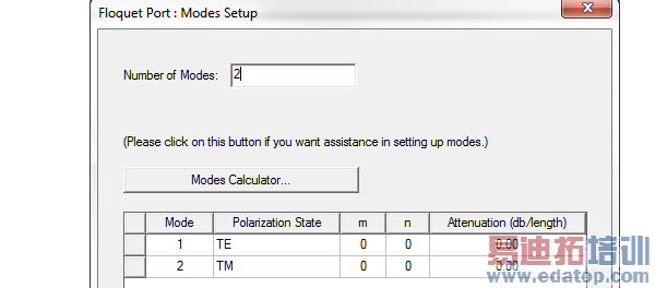
In general, Floquet modes are specified by two modal indices and a polarization setting. These designations resemble the textbook notation for rectangular waveguide modes, such as ``TE10''.
The default mode table specifies a pair of Floquet modes. The default modes both have modal indices equal to zero and are sometimes called the "specular" modes. Specular modes are always an essential part of the Floquet mode set, but sometimes one of the two polarizations may be omitted. For general frequency and scan conditions, other higher-order Floquet modes will be required. A modes calculator, invoked by selecting the Modes Calculator button, is available to set these up for the user.
The final column of the mode table is labeled "Attenuation". The numbers in the this column are computed by the modes calculator to help you decide which modes to keep. The values represent the modal loss in amplitude along the direction normal to the Floquet port plane in model units of dB per model unit length.
You should keep in mind that the displayed attenuation for a mode is a function of both the frequency and the scan angle set specified in the modes calculator. When the later includes more than one scan direction, the attenuation displayed is the "worst case" in that it is the least amount of attenuation experienced by the mode over all the specified scan directions.
Thus when the table gives a value of 0 dB, at one or more scan directions specified in the modes calculator the particular mode propagates without attenuation. Similarly, when the table displays, say 60 dB, a 60 dB per unit length is the least amount of attenuation at all specified scan directions. At any given direction, only the same or larger attenuations (for example, 70 dB per length) will occur.
4. It is generally good policy in terms of simulation efficiency as well as ease of interpretation of results, to eliminate any modes that are not necessary. Do this by editing the “Number of Nodes” value” in the Modes Setup tab.
Note that the list is trimmed from the bottom up.
5. To change the order of items in the final Modes list, drag each corresponding line by the square box at the left of each row.
6. Click Next for the Post Processing tab.
This panel contains settings which affect the fields once the field solution is complete.
7. To enable the Deembed settings, click the checkbox.
This enables the distance and units field for the positive distance to deembed into the port, or negative distance to deembed out of the port. To set the distance graphically, click the Get Distance Graphically button.
8. Click Next for the 3D Refinement tab.
This panel contains Affects Refinement checkboxes which allow you to specify Floquet modes in the 3D adaptive refinement process. Typically, you select no modes or only one or both specular (TE00 or TM00) modes. Selecting more than this may reduce the efficiency and accuracy of the solution process.
In 3D adaptive refinement the generated mesh is a compromise which simultaneously represents the 3D field patterns of every mode included in the adapt process. If the field patterns of certain modes represent the fields of interest and others do not, excluding the latter from the adapt process will result in a "targeted" mesh that better represents the excitation field pattern.
With this in mind, general guidelines follow. For antenna array simulations in which the active impedance or embedded-element pattern is sought, the Wave or Lumped ports modeling the feed structure provide the fields of interest. In this case, no Floquet modes should be included in the adapt process. On the other hand, if the per-cell RCS is of interest, one or both specular Floquet modes provide the fields of interest and should be included in the 3D adapt process by checking the corresponding Affects Refinement boxes. Similarly for a FSS simulation with two Floquet ports, specular modes provide the fields of interest and should be selected to participate in the 3D adapt process.
In certain simulations (for example, a frequency-selective surface) you will set up a second Floquet port. Note that when you do this that HFSS automatically copies the lattice vectors, modes table, and 3D refinement settings from the first Floquet port to the second.
HFSS 学习培训课程套装,专家讲解,视频教学,帮助您全面系统地学习掌握HFSS
上一篇:Assigning Magnetic Bias Sources
下一篇:Assigning Infinite Ground Plane Boundaries in HFSS-IE

