- 易迪拓培训,专注于微波、射频、天线设计工程师的培养
HFSS15: Importing GDSII Format Files
录入:edatop.com 点击:
See the introductory topic Importing 2D Model Files for the initial steps in the process of importing 2D data.
The process for importing GDSII format files into the HFSS or HFSS-IE uses a single dialog box:
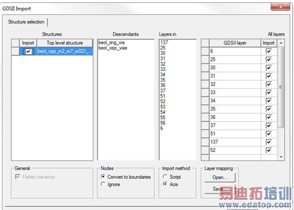
GDSII Structures Panel
The GDSII file may contain several top level structures.
1. Click on a structure name in the GDSII Structures panel to highlight it.
2. Clicking on the Select checkbox in the GDSII Structures panel both highlights the structure and selects that top-level structure to be imported.
When multiple structures are imported, HFSS or HFSS-IE creates multiple designs under the current project, one for each of the GDSII structures.
Descendants Panel
The GDSII file is hierarchical and may contain many sub-layouts. The Descendants panel shows the sub-layouts in the selected top-level designs.
Layers for structurename Panel
The Layers for structurename panel shows the layers for the (most recently) highlighted top level structure [structurename]. GDSII layers are identified by layer numbers.
All Layers Panel
The All Layers panel lists all the layers from all the structures in the file.
Use the Import check boxes in the All GDSII Layers panel to select the layers to import. You can drag and drop the layers in the list to change the vertical stackup of layers.
General Field
The Flatten hierarchy checkbox is automatically selected. HFSS always flattens any hierarchical geometry in the GDSII.
Nodes Field
GDSII supports nodes and boundaries as separate data types. Normally, boundaries represent polygons. HFSS can either convert objects that use the nodes data type to boundary types, or can ignore them. Use the radio buttons to select Convert to boundaries or Ignore. The default is to convert data type nodes to data type boundary.
Import Method Field
Use the radio button to select the import method as Script of Acis
Layer Mapping Field
If desired, you can create a mapping of the GDSII layer numbers to layer names in the design stackup. To create and use the mapping.
1. Use a text editor to create a text file that maps the GDSII layer numbers to layer names in the stackup. The layer mapping file must have a .tech suffix.
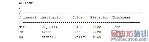
The .tech format:
• / is the comment character
• Units may be specified with a line UNITS <string> before the lines of layer information. <string> is any of the allowed desktop length units. The default units is nm.
• Each layer is specified by a line that contains <import layer> <product layer> <layer color> <layer elevation> <layer thickness>
where:
<import layer> - the name of the DXF layer
<destination layer> - the name to map the DXF layer to. This specifies the layout layer in Designer. In HFSS, it is used as part of the name for objects imported from this DXF layer.
<layer color> - A string from the choices listed here, for example. blue2
<layer elevation> - double
<layer height> - double
2. For example:
3. Click the Open button in the Layer mapping panel to locate and open an existing layer mapping file.
4. Click OK.
The file is imported into the active Modeler window.
You can use the Save button to save a layer mapping file with the current settings.
HFSS 学习培训课程套装,专家讲解,视频教学,帮助您全面系统地学习掌握HFSS
上一篇:Implementation Details for Custom Scheduler Integration
下一篇:Implicit Boundary Assignments

