- 易迪拓培训,专注于微波、射频、天线设计工程师的培养
HFSS15: Set Differential Pairs
录入:edatop.com 点击:
A differential pair represents two circuits, one positive and one negative routed close together so they will pick up nearly the same amount of noise. The two signals are subtracted from each other by a receiver, yielding a near "noise-free" version of the signal.
You can define one or more differential pairs from terminal excitations assigned on existing wave ports. Differential pairs can span ports, use lumped ports, and be enabled or disabled. To allow automated calculation of differential S-parameters from lumped ports, you can select terminals from two arbitrary ports, whether wave ports or lumped ports, for use in a differential pair.
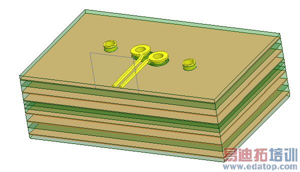
Because differential pairs can span ports or occur within a port, the Differential Pairs command is accessible at corresponding levels in the Project tree via the right click menu both at the Excitations level, and at the port name level. If a differential pair involves terminals from two different ports, the Differential Pairs command for those ports can only be accessed at the Excitations level. If an individual wave port has multiple terminals defined, the Differential Pairs command is enabled when you select that port and right click to display the shortcut menu. In order to combine differential pairs across ports, both ports must have the same renormalization setting; that is, either ports have Do not Renormalize on, or both have it off. For Transient Network solutions, differential pairs cannot include passive terminals. We will use a differential pair via model to assign the differential pairs. See Figure below.
To set up a differential pair:
1. Right-click Excitations in the Project tree and select Differential Pairs on the shortcut menu. Note: For a multi terminal wave port, select that port in the Project tree and click Differential Pairs on the shortcut menu.
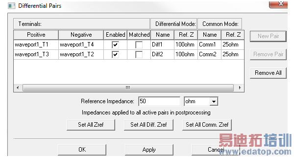
This displays the Differential Pairs dialog box. (For Transient Network designs, the Active Column is replaced by Enabled and Matched columns.) This contains table headers for the rows of values defined for each pair. It also contains a field for the renormalizing impedance value and units.
2. Click New Pair.
This adds existing pairs to the Terminals list, and sets default values for the Differential Mode and Common mode. All values can be edited.
It also lists which terminal is Positive, which is Negative. By selecting the dropdown menus in these fields, you can reassign these values.
The table row shows the checkbox for the newly defined pair as Enabled. Unchecking the box disables the definition for that pair. This can be useful if you later want to redefine terminal normalization, without having to remove the defined pair altogether.
3. If other pairs can be created from the existing Terminals, the New Pair button remains enabled.
4. Under Differential Mode headers in the table, do the following:
a. If desired, type a new name for the differential mode in the Name text box. The default base name is Diff. To specify a new default see: Setting Default Boundary/Excitation Base Names.
b. Unless the Post Processing tab selection for the Port is set to Do Not Renormalize, you can edit the renormalize impedance value here. You can either specify a real valued renormalizing impedance for the differential mode in the Ref. Z text box or use the Full Port Renormalizing Impedance text box and the Set All Diff. Zref. button or the Set All Zref button to set the values.
5. Under Common Mode headers in the table, do the following:
a. If desired, type a name for the common mode in the Name text box. The default base name is Comm. To specify a new default name, see Setting Default Boundary/Excitation Base Names.
b. Either specify a real valued renormalizing impedance for the common mode in the Ref. Z text box, or use the Full Port Renormalizing Impedance text box and the Set All Comm. Zref. button or the Set All Zref button to set the values.
6. If the New Pair button is enabled, you can define additional differential pairs.
You can use the command buttons in the Differential Pairs window to Remove Pair, or Remove All Pairs.
7. To accept the assignments, click OK to close the Differential Pairs dialog box.
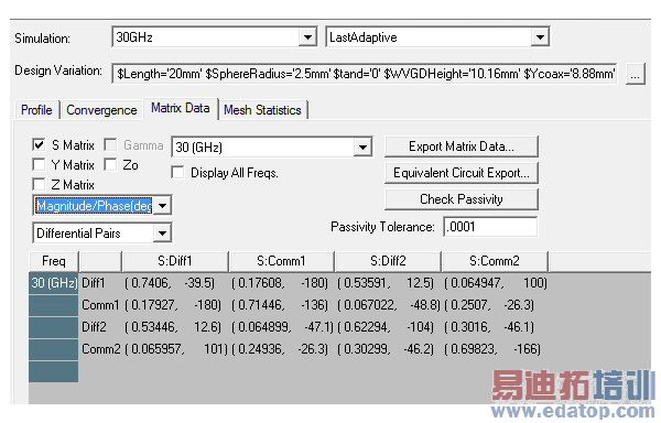
After HFSS has generated a solution, view the common and differential quantities of the differential pair under the Matrix tab of the Solution Data window as shown below.
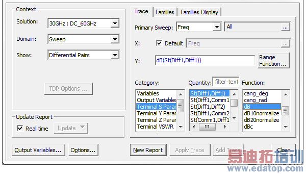
When the design has differential pairs (link), the reporter can display quantities for the defined pairs or for the single-ended terminals upon which they are based. A pull-down menu will appear in the Context area of the Report creation dialog which allows the user to select which quantities will be displayed.
.
You can freely mix differential and single-ended terminal quantities. However, single ended quantities are computed as if no differential pairs existed. So, in the unlikely case of several terminals where only a subset are combined into pairs, the results may not be as expected.

