- 易迪拓培训,专注于微波、射频、天线设计工程师的培养
HFSS15: Unit Cell of a Phased Array
录入:edatop.com 点击:
Description - A unit cell of an infinite phased array of vivaldi antennas is simulated using linked boundaries and a Floquet port.
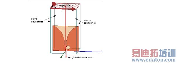
Model - the antenna is fed by a coax line with a wave port. The upper face of the unit cell is terminated in a Floquet port. The sides are two pairs of Master and Slave boundaries. The substrate er = 6 and is 1.27 mm thick. The conducting traces are 2D objects with PerE boundaries.
Setup - Adapt at 4.5 GHz with an interpolating sweep from 2 to 5 GHz.
Note | To view a port or boundary, select the desired item in the Project Tree. It is then highlighted in the Model window and the properties will be displayed in the Properties window. |
Post Processing
After solving, you can view solution data by right-clicking on Setup1 and selecting Profile to display the Solution dialog. You also view the Solution tabs for Convergence, Matrix Data, and Mesh Statistics.
To view a plot of active S parameter seen at the feed, look in the Project tree and double-click on XY Plot1. To view the modes present on the Floquet port click on the desired mode under Port Field Display>Floquet Port 1 in the Project tree, and a vector plot of the mode will be displayed.
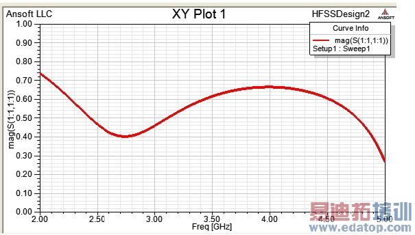
This design was analyzed in “Analysis of Periodic Structures via a Time-Domain Finite-Element Formulation with a Floquet ABC,” L.E.R. Peterson et al., IEEE Trans, AP, March 2006, pp 933-944. You will see the plot computed here agrees nicely with Fig. 9b in the reference.
HFSS 学习培训课程套装,专家讲解,视频教学,帮助您全面系统地学习掌握HFSS
上一篇:User Breaks Iteration Control
下一篇:Use the Relative Coordinate System in a Far Field Setup Calculation

