- 易迪拓培训,专注于微波、射频、天线设计工程师的培养
HFSS15: Spherical Vector Input Fomat
录入:edatop.com 点击:
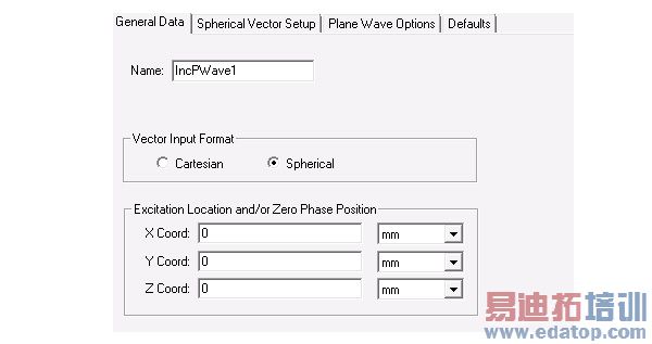
1. On the Incident Wave Source dialog box, select the radio button Spherical.
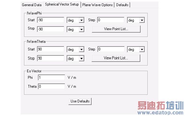
2. Click the Spherical Vector Setup and edit the IWavePhi, IWaveTheta, Eo Vector fields.
Note: If you enter values in the Step fields and click the View Point List button, you can see all the phi or theta values.
A spherical grid is created when q is swept through each f point. At each grid point, an incident wave is present traveling towards the origin of the coordinate system for the design. The number of incident waves and grid points can be calculated by multiplying the number of f points by the q points.
Note: Only a single incident wave angle can be defined for periodic structures which are defined with master and slave boundaries.
Note: Whenever additions/changes are made to incident waves that affect fields, it invalidates those solutions that can possibly have fields. Meshes are not invalidated.
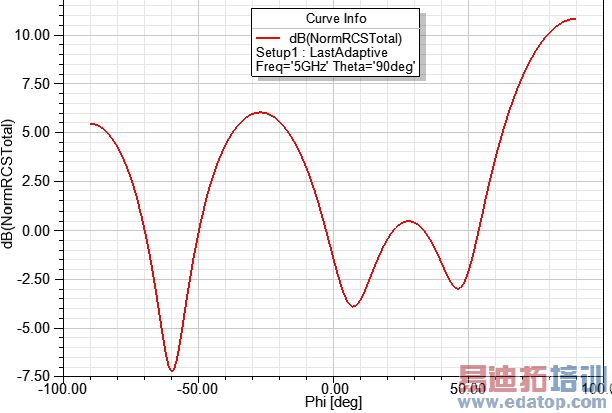
The plot of the RCS of a dielectric sphere for an incident regular/propagating plane wave are shown below.
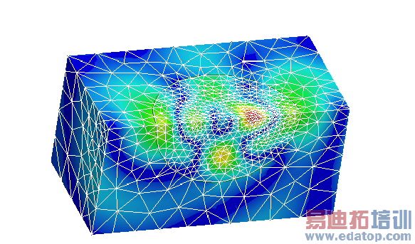
The Mesh Plot and the field are as shown in the figure below. The mesh is denser where the field is high due to the adaptive meshing feature in HFSS.
HFSS 学习培训课程套装,专家讲解,视频教学,帮助您全面系统地学习掌握HFSS
上一篇:Specifying the Number of Compute Resource Units for HPC Jobs
下一篇:Specifying the Number of Processors

