- 易迪拓培训,专注于微波、射频、天线设计工程师的培养
如何对锂离子电池进行高效率的充电(三)
录入:edatop.com 点击:
Since the size of the battery charger is very critical for portable devices, the output inductor is required to be as small as possible. For a given inductor ripple current, the required inductance is given by 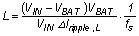
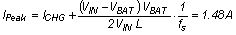
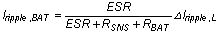
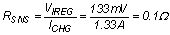
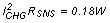
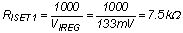
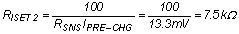
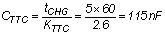
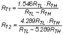
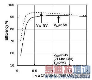
Figure 5: 1MHz synchronous switching charger efficiency
Where fs and ΔIripple,L are the switching frequency and inductor ripple current, respectively. Substituting VIN=12 V, VBAT=6.0 V (3.0 V/cell), ΔIripple,L=30 percent ICHG, ICHG=1.33 A and fs=1 MHz into the above equation yields L=7.5 μH. Selecting a 10-μH shielded inductor. Note that the shielded inductor has better capability to restrain the magnetic flux within the inductor and minimize the radiated electromagnetic interference (EMI). It is shown that the required inductance is inversely proportional to the switching frequency. The inductance can be 10 times smaller and it has a smaller size at 1 MHz than at 100 kHz On the other hand, the higher the switching frequency, the higher the switching loss across Q1 and Q2 and the higher the core loss in the inductor as well. Therefore, 1MHz switching frequency is a good compromise for a practical design between inductor size and power conversion efficiency.
Selecting inductor current rating is also critical for achieving desired efficiency. The peak inductor current IPeak is calculated by:
The inductor has maximum ripple current when the battery voltage is half of the input voltage. Therefore, the inductor saturation current rating should be always higher than the maximum peak inductor current at all operating conditions.
It is important to select a small ESR ceramic output capacitor with good temperature characteristics such as X7R and X5R ceramic capacitor. The ripple current flowing into the battery is given by
Where ESR, RSNS and RBAT are the equivalent series resistance of the output capacitor, current-sensing resistor and battery internal impedance including the Rdson of the protection MOSFETs in the battery pack, respectively. The smaller the ESR of the output capacitor, the smaller the ripple current going to the battery. The ripple current to the battery should be designed less than one-tenth of the inductor ripple current and a 10 μF/10 mΩ ESR ceramic capacitor is usually enough to meet this requirement.
* Select the current sensing resistor RSNS
Choose RSNS based on the regulation threshold VIREG across the sensing resistor. Let VIREG=133mV for achieving standard sensing resistor value. Solve for RSNS
The power dissipation across the sensing resistor is
* Select 1206 size rated at 0.5 W.
* Select fast charge current set resistor RSET1. RSET1 is used to set the fast charge current, RSET1 is given by:
* Select pre-charge current set resistor RSET2. RSET2 is used to set the pre-charge current and is determined by:
* Select the maximum charge time set capacitor CTTC The charge timer detects the “bad” battery pack if the battery has not been fully-charged when the charge timer is expired. CTTC is used to program the charge timer and it provides 2.6minute per nF.
Choose a 0.1 μF ceramic capacitor.
* Select minimum and maximum battery charge temperature set resistors RT1 and RT2 RT1 and RT2 are used to program the battery charge temperature range between 0°C and 45°C for initiating the battery charger. For a commonly used 103AT-2 thermistor in the battery pack, RT(0°C)=RTL=27.28kΩ, RT(45°C)=RTH=4.911 kΩ, the RT1 and RT2 are determined by:
Substituting RTL and RTH into the above equations yields RT1=9.31 kΩ and RT2=442 kΩ.
Figure 5 shows the efficiency curves with various input voltages. It is shown that it has over 90 percent efficiency even at 16-V input voltage. Compared with the linear charger, the power dissipation is much smaller and it is possible to design the synchronous-switching charger in the battery pack’s side to minimize the use of mother board’s real estate since the inductor size is small due to MHz frequency operation. One important thing to remember is that the battery’s service life is strongly dependent on its temperature. Charging the Li-Ion battery with synchronous switching charger basically generates less heat. As a result, it has longer service cycle-life compared with the linear charger.
Figure 5: 1MHz synchronous switching charger efficiency
Conclusion
The linear charger is suitable for the low-capacity battery charge applications with low cost and small size advantages. Continuing power demand increases from portable devices such as portable DVD players and smart phones, making the linear battery charger no longer efficiently adequate to charge the Li-Ion battery due to its inherent high power dissipation limitation. A high-efficiency synchronous switching battery charger with integrated MOSFETs provides an efficient charging solution for those advanced portable devices with less heat and longer battery service life.
Author Info
Jinrong Qian is an applications manager and senior member of technical staff for the portable power battery management group at Texas Instruments. He has published more than 30 peer-reviewed power electronics journal and conference papers and holds 19 U.S. patents. Dr. Qian’s primary research interests include high-efficiency power converter topologies, portable power supply design and battery power management ICs and their applications. Dr. Qian was an Associate Editor of the IEEE Transactions on Power Electronics from 1999 to 2001 and a senior member of IEEE in 1999. He earned a bachelors of science degree in Electrical Engineering from Zhejiang University and a Ph. D. from Virginia Polytechnic Institute and State University.
Jinrong Qian, Senior Member of Technical Staff, Portable Power Battery Management Applications Manager Texas Instruments, 12500 TI Blvd, MS8709, Dallas, TX75243
上一篇:平台式存储器控制器的考量及实作
下一篇:如何对锂离子电池进行高效率的充电(二)