- 易迪拓培训,专注于微波、射频、天线设计工程师的培养
CST2013: Time Signal View
录入:edatop.com 点击:
Here, you may view your simulation’s time signals. The naming convention for the time signals differs, depending on whether simultaneous port mode excitation or sequential port mode excitation is activated.
Naming Convention for Time Signals with Sequential Port Mode Excitation
|
|
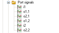
One single mode per port:
| Waveguide port, discrete port, or nearfield source input signals start with i, output signals start with o, and the numbers describe the port where the signal is recorded and which port was stimulated. The labels are also listed on the right-hand side of the main plot window, each color associated to a displayed curve. |
Multiple modes per port:
| If multiple modes are excited per port, the signal labels are extended by the mode number in round brackets. The mode numbers are located directly behind the port number. |
Plane wave excitation:
| The label "Plane wave" indicates the excitation time signal of a plane wave. |
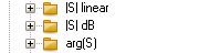
S-Parameter:
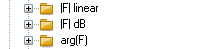
| The behavior of the port signals in frequency domain is presented in the corresponding subfolders. |

Naming Convention for Time Signals with Sequential Port Mode Excitation
One single mode per port:
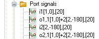
| In addition to the naming convention for sequential port mode excitation, the labels for the input and output signals are extended by the excitation amplitude and phase shift / reference frequency setting with respect to the time delay setting if automatic labeling is turned on in the Port Mode Excitation Selection dialog. |
Multiple modes per port:
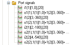
| If multiple modes are excited per port, the signal labels are extended by the mode number in round brackets. The mode numbers are located directly behind the port number. Every mode of the different ports can be stimulated independently by a different excitation signal. If the stimulating signal is not the project's reference signal, the name of this excitation signal is also included in the port mode control sequence. Because this naming procedure leads to very long control sequences, it is advisable to use user-defined labels. An example is shown below. |
Normalized DFT magnitudes and phases:
| The behavior of the port signals in frequency domain is presented in the corresponding subfolders. |
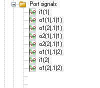
Example
The following two examples point out the naming convention for time signals with simultaneous port excitation activated. The upper example uses a phase shift definition with a reference frequency of 20; the lower example uses an equivalent time delay definition. Port 1 is stimulated with the reference signal, therefore no information about the excitation signal is displayed. The both modes of port 2 are stimulated with the excitation signal signal1 that is indicated by displaying the excitation signal's name in the port mode control sequence.
CST培训课程推荐详情>>
 最全面、最专业的CST微波工作室视频培训课程,可以帮助您从零开始,全面系统学习CST的设计应用【More..】
频道总排行
- CST2013: Mesh Problem Handling
- CST2013: Field Source Overview
- CST2013: Discrete Port Overview
- CST2013: Sources and Boundary C
- CST2013: Multipin Port Overview
- CST2013: Farfield Overview
- CST2013: Waveguide Port
- CST2013: Frequency Domain Solver
- CST2013: Import ODB++ Files
- CST2013: Settings for Floquet B