- 易迪拓培训,专注于微波、射频、天线设计工程师的培养
HFSS15: Waveport Placement
录入:edatop.com 点击:
HFSS treats each port that you define to be connected to a semi-infinitely long waveguide or transmission line that has the same cross-section and properties as the wave port. The placement of the wave port is critical because it can affect the accuracy of the solutions. If the wave port is close to a discontinuity due to change in shape, dimension, or material of a structure the resulting 3D field can be a superposition of propagating and non-propagating modes.
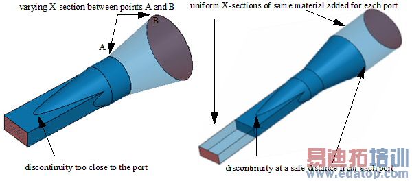
Hence, the first discontinuity should be at an appropriate distance away from the port surface. This allows any energy reflected into an evanescent mode of the port to decay before reaching the port. Without this separation the resulting accuracy of the S-parameters will be compromised. To precisely determine a distance you can solve the 'port only' with one additional mode (for a correct port definition this mode will be evanescent) and extract the decay length of this mode from its complex gamma. Then, as a rule of thumb, place the first discontinuity at least three times this decay length. Such rigor is not usually necessary and experience over time will give you a solid understanding of typical spacings for their port geometries and frequencies of analysis.
Number of Modes
The electrical size of a port at the highest frequency of interest determines the number of modes to be included in the port definitions. If the guidelines on discontinuity discussed above are followed, the number of modes equals the number of propagating modes at the highest frequency; if they are not followed then, the port as a boundary condition will not be accurate. Regardless of whether they are propagating or not, the solver will solve these modes for calculating the S-parameters.
HFSS 学习培训课程套装,专家讲解,视频教学,帮助您全面系统地学习掌握HFSS
上一篇:Wave Port Dialog for Modal Solutions
下一篇:Where the Solvers Apply Scattered or Total Field Formulations

