- 易迪拓培训,专注于微波、射频、天线设计工程师的培养
HFSS15: Assigning Finite Conductivity Boundaries
录入:edatop.com 点击:
A finite conductivity boundary the behavior of the field at the object surface. The finite conductivity boundary is valid only if the conductor being modeled is a good conductor, that is, if the conductor’s thickness is much larger than the skin depth in the given frequency range.
To assign a Finite Conductivity boundary:
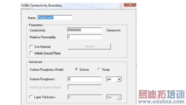
1. Select a surface on which to assign the boundary and click HFSS>Boundaries>Assign>Finite Conductivity to bring up the Finite Conductivity Boundary dialog box.
2. Do one of the following:
• Enter the conductivity in inverse ohm-meters, and then enter the permeability.
• Select Use Material, click the default material name button , and then choose a material from the material editor. The conductivity and permeability values of the material you select will be used for the boundary. Note that selecting a perfectly conducting material for a finite conductivity boundary triggers a validation error.
3. Select Infinite Ground Plane if you want the surface to represent an electrically large ground plane when the radiated fields are calculated during post processing.
Note that if you select Infinite Ground Plane, the effect of the finite conductivity boundary will be incorporated into the field solution in the usual manner, but the radiated fields will be computed as if the lossy ground plane is perfectly conducting.
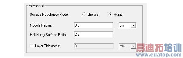
4. To select the Surface Roughness Model used for surfaces such as the interface between the conductor and the substrate for a microstrip line, select either Groisse or Huray.
For the Groisse model , you specify a Surface Roughness parameter (traditional case) as a value (or variable) and units. The default is 0 um. Legacy projects use the Groisse model by default.
For the Huray Model, you specify the Nodule radius value (or a variable), which describes the radius of copper spheres that model the surface roughness. The default is 0.5 um. Also for the Huray model, you specify the Hall-Huray Surface Ratio, a unitless quantity. The default is 2.9.
(Using surface roughness with the Finite Conductivity boundary may be more intuitive than using a layered impedance boundary to model the effects.)
5. To specify a layer thickness, click the checkbox to enable the Layer Thickness field, and enter a value and select units.
Note | You can assign a variable as the conductivity or permeability values or roughness model parameters. |
HFSS 学习培训课程套装,专家讲解,视频教学,帮助您全面系统地学习掌握HFSS
上一篇:Assigning Lumped Ports for Terminal Solutions
下一篇:Assigning Impedance Boundaries

