- 易迪拓培训,专注于微波、射频、天线设计工程师的培养
HFSS15: Assigning Impedance Boundaries
录入:edatop.com 点击:
An impedance boundary represents a resistive surface. The behavior of the field at the surface and the losses generated by the currents flowing inside the resistor are computed using analytical formulas; HFSS does not actually simulate any fields inside the resistor. For HFSS-IE, impedance boundaries should not be used as a transmission condition.
To assign an impedance boundary:
1. Select a surface on which to assign the boundary and click HFSS or HFSS-IE>Boundaries>Assign>Impedance to bring up the Impedance Boundary dialog box.
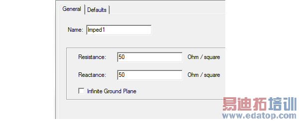
2. Enter the Resistance and Reactance.
3. For HFSS designs you can select Infinite Ground Plane if you want the surface to represent an electrically large ground plane when the radiated fields are calculated during post processing. HFSS-IE does not support infinite ground plane for impedance boundaries.
Note that if you select Infinite Ground Plane, the effect of the impedance boundary will be incorporated into the field solution in the usual manner, but the radiated fields will be computed as if the lossy ground plane is perfectly conducting. Only one infinite ground plane is permitted in designs with impedance boundaries.
Note | You can assign a variable as the resistance and reactance values. Eigenmode designs cannot contain design parameters that depend on frequency, for example, a frequency-dependent impedance boundary condition. |
HFSS 学习培训课程套装,专家讲解,视频教学,帮助您全面系统地学习掌握HFSS
上一篇:Assigning Finite Conductivity Boundaries
下一篇:Assigning Lumped RLC Boundaries

