- 易迪拓培训,专注于微波、射频、天线设计工程师的培养
HFSS15: Assigning Finite Conductivity Boundaries in HFSS-IE
录入:edatop.com 点击:
A finite conductivity boundary approximates the behavior of the field at the object surface.
The finite conductivity boundary is valid only if the conductor being modeled is a good conductor, that is, if the conductor’s thickness is much larger than the skin depth in the given frequency range.
To assign a Finite Conductivity boundary:
1. Select a surface on which to assign the boundary and click HFSS-IE>Boundaries>Assign>Finite Conductivity to bring up the Finite Conductivity Boundary dialog box.
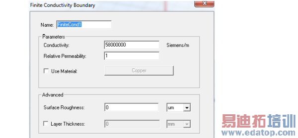
2. Do one of the following:
• Enter the Conductivity and the Relative Permeability.
• Select Use Material, click the material name button, and then choose a material from the material editor. The conductivity and permeability values of the material you select will be used for the boundary. Note that selecting a perfectly conducting material for a finite conductivity boundary triggers a validation error.
3. To specify the roughness of surfaces such as the interface between the conductor and the substrate for a microstrip line, enter a value for Surface Roughness and select the units (default, microns) from the pull down menu.
(This may be more intuitive than using a layered impedance boundary to model the effects.)
4. To specify a layer thickness, click the checkbox to enable the Layer Thickness field, and enter a value and select units..
Note | You can assign a variable as the conductivity or permeability values. |
HFSS 学习培训课程套装,专家讲解,视频教学,帮助您全面系统地学习掌握HFSS
上一篇:Assigning Lumped RLC Boundaries
下一篇:Assigning Incident Waves

