- 易迪拓培训,专注于微波、射频、天线设计工程师的培养
HFSS15: Assigning Lumped RLC Boundaries
录入:edatop.com 点击:
A lumped RLC boundary represents a parallel combination of lumped resistor, inductor, and/or capacitor applied to a surface. Multiple RLC boundaries can be used to model other circuit configurations. For example, a lumped RLC serial circuit connection can be modeled with three connected RLC surfaces: one with only resistance, one with only inductance, and one with only capacitance.
To create a lumped RLC boundary:
1. Select a surface on which to assign the boundary and click HFSS or HFSS-IE>Boundaries>Assign>Lumped RLC to bring up the Lumped RLC Boundary dialog box.
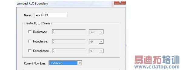
2. Select Resistance, Inductance, and Capacitance as needed and specify values and units for each selected element. Optionally, you can assign a variable to any of these values.
3. To specify where on the surface the current and voltage will be controlled, define a Current Flow Line. The selection field initially appears as Undefined. Select New Line to define a vector line on the boundary surface.
Note | HFSS and HFSS-IE assume the lumped RLC is assigned to a rectangular face. If you assign a non-rectangular face, HFSS and HFSS-IE issue a warning, but proceed with the solution. Using a non-rectangular face can result in less accurate representation of the lumped RLC. See the technical notes on RLC boundaries for more information. |
HFSS 学习培训课程套装,专家讲解,视频教学,帮助您全面系统地学习掌握HFSS
上一篇:Assigning Impedance Boundaries
下一篇:Assigning Finite Conductivity Boundaries in HFSS-IE

