- 易迪拓培训,专注于微波、射频、天线设计工程师的培养
HFSS15: Assigning Radiation Boundaries
录入:edatop.com 点击:
For Eigenmode, Driven Modal or Driven Terminal Designs
A radiation boundary is used to simulate an open problem that allows waves to radiate infinitely far into space, such as antenna designs. HFSS absorbs the wave at the radiation boundary, essentially ballooning the boundary infinitely far away from the structure. In HFSS, these are sometimes described as Absorbing Boundary Condition, or ABC.
A radiation surface does not have to be spherical, but it must be exposed to the background, convex with regard to the radiation source, and located at least a quarter wavelength from the radiating source. In some cases the radiation boundary may be located closer than one-quarter wavelength, such as portions of the radiation boundary where little radiated energy is expected.
Note | Whenever additions/changes are made to radiation boundaries that affect fields, it invalidates those solutions that can possibly have fields. Meshes are not invalidated. |
To assign a radiation boundary:
1. Select a surface on which to assign the boundary and click HFSS >Boundaries>Assign>Radiation to bring up the Radiation Boundary dialog box.
2. If your project uses a field solution from another source, your "target" project must have radiation boundaries with Advanced Options defined in order to specify where the fields from the "source" project enter. See the discussion here.
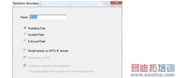
3. Designate the boundary as either:
• Radiating Only - this refers to the original radiating surface properties (the default). If you select this option, the scattered field formulation is applied. (See Technical Notes). If you do not select this radio button the total field formulation is applied. (See Technical Notes).
• Incident Field - the incident field source patterns are projected on these surfaces and are backed by ABC or PML. This is like a generalized space port. HFSS knows the incident field pattern, applies it to the port and expects a reflected field pattern which radiates back. In other words, it behaves as if you excited the project by a Norton or Thevenin generator using an impedance which is the free space wave impedance.
• If you select Radiating Only or Incident Field, you can also specify whether the surface is used as Reference for FSS, that is, as a Frequency Selective Surface - this surface become the input surface for calculations of the reflection/transmission coefficients. The other radiating surface automatically becomes output. Only one FSS can be defined in a given model. Using the Incident Field option together with Reference for FSS is advantageous for highly reflective and resonant structures. Reflection/Transmission coefficients for FSS designs can be viewed in the solution data panel as S-parameters or you can create an S-parameter report.
• Enforced Field - this has the H tangential component of the incident field directly applied on these surfaces. It is an inhomogeneous Newmann BC. In other words, it behaves as if you excited the project by an ideal current source (enforced current). If you select Enforced Field, the Use IE Formulation option is grayed out.
• Model Exterior as HFSS-IE Domain- this uses integral equation formulation, which is an exact transparent condition. By taking advantage of conformal radiation volumes to reduce the overall finite element solution domain utilization of the IE boundary will result in more efficient simulation for electrically large open boundary problems. It can be close to or on the structures, but for performance, 0.05 wavelength is recommended. If it is on a surface, you must turn off curvilinear elements. The IE boundary should enclose the entire structure by itself, or with an Infinite ground plane. (Compare Assigning IE Regions). If you model a radiation boundary as an IE domain, the solution setup cannot include calculations of derivatives on those regions.
• Include for nearfield/far field calculation - If you select Radiation Only, the Include in near/far field calculation option is grayed out but checked. That information passes to the solver to detect if the boundary is internal. This is necessary for incident wave problems. All Radiation Only surfaces are included in the near/far field calculation.
When you select Incident Field or Enforced Field, you can designate that the surface is included in near/far field calculation by checking. If you do not include any surfaces in the near/far field calculation (whether as Radiating Only, or by checking), when you select default radiation surfaces at the near/far field calculation setup panel an error message states that “No radiating surface has been selected.”
Note | If you select either Enforced Field or Incident Field you should run a validation check in order to avoid an invalid setup. The setup is invalid if any of these surfaces are internal. If you select either Enforced Field or Incident Field in most cases, you should avoid internal surfaces. In order to do that, internal objects with Enforced/Incident Field BC should be substructed to become background, or PEC material should be assigned to these objects to become "NoSolveinside". |
Note | Do not define a surface that cuts through an object to be a radiation boundary. In general, do not define the interface of two internal objects to be a radiation boundary. The only exception is when one object is a perfectly matched layer boundary (PML) and the other is the PML base object. |
HFSS 学习培训课程套装,专家讲解,视频教学,帮助您全面系统地学习掌握HFSS
上一篇:Assigning Frequency Dependent Material: Piecewise Linear Input
下一篇:Assign Lumped Ports for Modal Solutions

