- 易迪拓培训,专注于微波、射频、天线设计工程师的培养
HFSS15: Assign Lumped Ports for Modal Solutions
录入:edatop.com 点击:
While assigning lumped ports for modal solutions, you will be prompted to set the complex full port impedance which must be non-zero, set the non-negative resistance, and finally define the integration line for the single mode. The steps are as follows:
1. Select a surface to which you want to assign the port and click HFSS or HFSS-IE>Excitations>Assign>Lumped Port to bring up the Lumped Port: General dialog box.
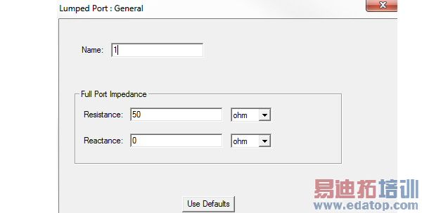
2. Define the complex Full Port Impedance in the Resistance and the Reactance fields.
Note: The reference impedance is meant to represent the component modeled by the lumped port. You can assign a variable to these values. This variable can be dependent on the frequency, which allows use of a dataset for frequency dependent impedance.
3. Click Next to display the Lumped Port: Modes dialog box.
Note: The field Number of Modes is not editable because only one mode is allowed.
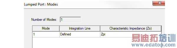
4. Integration line must be drawn for a lumped port.
The Characteristic Impedance (Zo) column shows the Zpi method usually used to calculate the characteristic impedance. If Zpi is zero, HFSS uses Zpv.
For definitions of how HFSS defines these values, see Calculating the Zpi , and Calculating the Zpv.
HFSS 学习培训课程套装,专家讲解,视频教学,帮助您全面系统地学习掌握HFSS
上一篇:Assigning Radiation Boundaries
下一篇:Assigning Screening Impedance Boundaries

