- 易迪拓培训,专注于微波、射频、天线设计工程师的培养
HFSS15: Assigning Screening Impedance Boundaries
录入:edatop.com 点击:
Planar screens or grids of large extent with periodic geometry can be replaced by a screening impedance boundary. The boundary applies a homogeneous characteristic impedance to the surface in an effort to create an equivalent electrical representation of the geometric grid pattern.
To assign a Screening Impedance boundary
1. Select a surface on which to assign the boundary and click HFSS >Boundaries>Assign>Screening Impedance to bring up the Screening Impedance Boundary dialog..
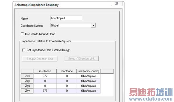
2. If the boundary requires anisotropic impedance, click the check box.
Checking the Anisotropic Impedance box enables the Coordinate System drop-down menu. This menu lists the Global Coordinate system and any relative coordinate systems if you have defined them in the design. Select the Coordinate System that defines the anisotropic characteristic of the impedance boundary. (See Creating a Relative Coordinate System.)
Note | An anisotropic boundary must not touch ports in a design. |
3. Click Next or the Screening Impedance tab, depending on the general option setting.
4. If you want to use an external design to define the screening impedance, click the Get Impedance from External Design checkbox to enable the Setup Link button. If you defining an anisotropic impedance, there will be two buttons: Setup X Direction Link and Setup Y Direction Link.
5. If you have not selected Use External Design, the Resistance and Reactance fields are enabled.
In these fields, you set the Resistance and Reactance. If Anisotropic Impedance is checked, the wizard shows Resistance and Reactance fields for X Axis alignment and Y axis alignment.
HFSS 学习培训课程套装,专家讲解,视频教学,帮助您全面系统地学习掌握HFSS
上一篇:Assign Lumped Ports for Modal Solutions
下一篇:Assign Lumped Ports for Terminal Solutions

