- 易迪拓培训,专注于微波、射频、天线设计工程师的培养
HFSS15: Assign Near Field Wave
录入:edatop.com 点击:
This section describes the Near Field Wave Options panel on the Incident Wave Source dialog box and how to assign near field waves. The following designs illustrate different ways of using near field sourcing to run a range of analyses on a dish antenna fed by a circular horn antenna.

First we will bring up the Near Field Wave Options panel and then, assign Near Field Wave.
1. Click HFSS>Excitations>Assign>Incident Wave>Near Field Wave.
Note: If you are using HFSS-IE go to HFSS-IE>Excitations>Assign>Near Field Wave
The Incident Wave Source : General Data dialog box appears.
2. Fill in the Excitation name and click Next to acccess the Near Field Wave Options panel.
Note: For array problems, the Active option includes the effects of the Near Field in the simulation. To disable the effects, uncheck the Active option.
3. Determine whether you want to use a linked design or an external data file. If you are using a linked design go to step 4. If you are using an external data file, go to Access Near Field External Data File and follow the instructions.
4. Click the Setup Link button on the Incident Wave Source dialog to specify the linked design.
Note: It is through the Setup Link dialog box that you will link the source design to your target design.
5. On the Setup Link dialog box select the radio button Edit Link.
The fields in the dialog box become active and editable as shown below.

6. Select the product in which you created your source design from the Product drop down list.
Note: Only HFSS, Maxwell, and SIWave appear in this list. An HFSS-IE project can be used as target but not as source; so it is not listed.
7. Specify the project that has the source design in one of the following ways:
a. Check Use This Project to pick a design from a current working project.
b. Click the ellipsis and browse your computer to pick the design.
Note | The option The project directory of selected product points to the default project directory location relative to the product that you selected from the drop-down menu. This is the same project directory that you set on the General Options dialog under Tools>Options. This option is useful especially, when you link across different products. The option This project points to the directory relative to where your current working project is located. |
8. Pick the source design from the Source Design drop-down menu which lists all the designs in the specified project.
9. Pick the setup type from the Source Solution pull-down menu (e.g. Last Adaptive, or Sweep, etc.).
10. Select the last two checkboxes as needed and click OK.
Note | For information about the option Force source design to solve in the absence of linked data in the target design, go to Convergence of Source Design. |
Preserve source design solution
This is the last option on the Setup Link dialog box. When the source design is closed or it is not included in the project manager window containing the target design, then the source design will not be saved. However, if you select this option, which is especially when you are using Maxwell or SIWave the source design is saved.

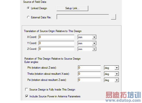
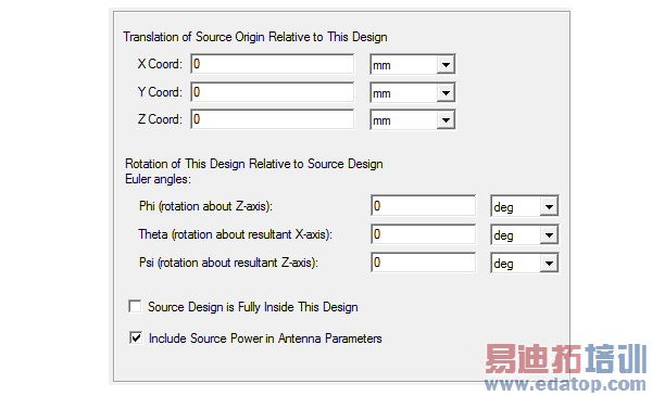
11. Close the Setup Link dialog, and if necessary, specify the Translation of Source Origin Relative to This Design on the Near Field Wave Options panel of the Incident Wave Source dialog box.
12. If required check the option Source Design is Fully Inside This Design.
When a source design is totally inside the target design, it should not be included into the near/far field calculation. If it is totally outside, the far field calculation should also integrate over the radiation surfaces of the source project.
13. If required check Include Source Power in Antenna Parameters.
The antenna parameters include power-related entries such as incident power, accepted power, radiated power. If you check Include Source Power in Antenna Parameters the antenna parameters in the design that receives the fields from a source design will be based on a power set for the excitations in the source design under HFSS>Fields >Edit Sources. For instance, this can be the power with which a port in a source antenna is excited. If the antenna in a source design is excited with 10 W, then the antenna parameters panel in the receiving design will show an incident power of 10 W.
Note | For more information on how to obtain antenna parameters during post processing, see Computing Antenna Parameters. |
14. Click Finish to close the dialog. The Near Field wave source point and direction is highlighted in the modeler window, and the wave appears in the Excitations list in the Project.
HFSS 学习培训课程套装,专家讲解,视频教学,帮助您全面系统地学习掌握HFSS
上一篇:Assigning Skin Depth-Based Mesh Refinement on Object Faces
下一篇:Assigning Slave Boundaries

