- 易迪拓培训,专注于微波、射频、天线设计工程师的培养
HFSS15: Antennas on Mast
录入:edatop.com 点击:
Description - Three dipole antennas mounted on an aluminum mast, simulated in HFSS-IE. The mast is mounted on an infinite ground plane.
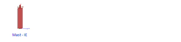
Model - The mast is 3.1 m high. The dipoles are modeled using 2D objects with a PerfE boundary. The excitations are lumped ports and the mounting structures are modeled by the polystyrene rods. Note under Boundaries in the Project tree, InfGndPlane1.
Setup - Adapt at 0.9 GHz.
|
Note |
To view a port or boundary, select the desired item in the Project Tree. It is then highlighted in the Model window and the properties will be displayed in the Properties window. Selecting an object in the History tree will also display its properties. |
Post Processing Antennas Mounted on a Mast
After solving, you can view solution data by right-clicking on Setup1 and selecting Profile to display the Solution dialog. You also view the Solution tabs for Convergence, Matrix Data, and Mesh Statistics.
Before viewing the fields make sure all three antennas are excited. Go to HFSS-IE>Fields>Edit Sources and uncheck all Terminated options. Set Scaling Factor to 1 for all three ports.
To view the radiation pattern shown, double click on Radiation Pattern 1 under Results in the Project tree. This is the q = 90o pattern cut.
To view the induced currents on the mast, double click on Mag_J1 under Field Overlays>J Fields.
HFSS 学习培训课程套装,专家讲解,视频教学,帮助您全面系统地学习掌握HFSS
上一篇:ANSYS EM - ANSYS Multiphysics Coupling
下一篇:ANSYS EM CAD Integration through Workbench

